11 - 1
11 - 1
AMP BOARD
-subwoofer
TABLE OF CONTENTS
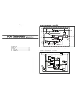
Internal IC Diagram ........................................................................... 11-1
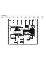
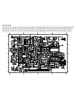
Circuit Diagram .................................................................................. 11-2
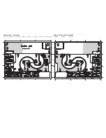
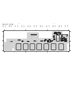
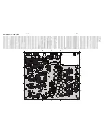
PCB Layout Top View ....................................................................... 11-3
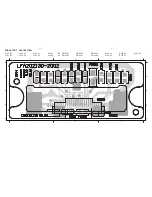
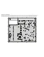
PCB Layout Bottom View .................................................................. 11-4
INTERNAL IC DIAGRAM - TAS5508APAG
INTERNAL IC DIAGRAM - DSP56371
PLL
OnCE™
Clock
Gen-
erator
YAB
XAB
PAB
YDB
XDB
PDB
GDB
MODB/IRQB
MODC/IRQC
MODD/IRQD
DSP56300
12
24-Bit
DDB
DAB
Peripheral
Core
Y
M
_E
B
X
M
_E
B
P
M
_E
B
P
IO
_E
B
Expansion Area
JTAG
4
5
RESET
MODA/IRQA
PINIT/NMI
EXTAL
Address
Generation
Unit
Six Channel
DMA Unit
Program
Interrupt
Controller
Program
Decode
Controller
Program
Address
Generator
Data ALU
24 × 24+56→56-bit MAC
Two 56-bit Accumulators
56-bit Barrel Shifter
Power
Mgmt.
Memory Expansion Area
X Data
RAM
36K × 24
Y Data
RAM
48K × 24
Bootstrap
ROM
Internal
Data
Bus
Switch
SHI
Triple
ESAI
ESAI_1
EFCOP
Interface
Timer
Interface
Interface
12
2
GPIO
11
ROM
32K × 24
ROM
32K × 24
Program
RAM
4K × 24
ROM
64K × 24
DAX
2
Power Supply
VR_
P
LL
AVDD_
P
LL
AV
SS
_
P
LL
AVDD_REF
VBGA
P
VRA_
P
LL
VRD_
P
LL
DVDD
DV
SS
AVDD
AV
SS
MCLK
XTL_OUT
XTL_IN
PLL_FLTM
PLL_FLTP
OSC CAP
SCLK
LRCLK
SDIN1
SDIN2
SDIN3
SDIN4
SDA
SCL
RESET
PDN
MUTE
HP_SEL
BKND_ERR
12C
Serial
Control
I/F
C
lo
ck,
P
LL,
and
Ser
ial
Dat
e I/F
Device
Control
Sy
stem
C
ontrol
DA
P C
ont
rol
PWM C
ontrol
8x8
C
ro
ssb
er
Mix
er
8x2
C
ro
ssb
er
Mix
er
8
8
4
8
8
8
2
2
0
Det
7
Blquads
Soft
Tone
Soft
Vol
Loud
Comp DRC
0
Det
7
Blquads
Soft
Tone
Soft
Vol
Loud
Comp DRC
0
Det
7
Blquads
Soft
Tone
Soft
Vol
Loud
Comp DRC
0
Det
7
Blquads
Soft
Tone
Soft
Vol
Loud
Comp DRC
0
Det
7
Blquads
Soft
Tone
Soft
Vol
Loud
Comp DRC
0
Det
7
Blquads
Soft
Tone
Soft
Vol
Loud
Comp DRC
0
Det
7
Blquads
Soft
Tone
Soft
Vol
Loud
Comp DRC
0
Det
7
Blquads
Soft
Tone
Soft
Vol
Loud
Comp DRC
9
Volume
Control
DC
Block
De
Emph Interpolate SRC NS PWM
DC
Block
De
Emph Interpolate SRC NS PWM
DC
Block
De
Emph Interpolate SRC NS PWM
DC
Block
De
Emph Interpolate SRC NS PWM
DC
Block
De
Emph Interpolate SRC NS PWM
DC
Block
De
Emph Interpolate SRC NS PWM
DC
Block
De
Emph Interpolate SRC NS PWM
DC
Block
De
Emph Interpolate SRC NS PWM
PWM Section
PSVC
Outpu
t C
o
ntrol
PWM_MPP and MR
PWM_MPP and ML
PWM AP and AM2 R Front
PWM AP and AM1 L Front
PWM AP and AM3 L Rear
PWM AP and AM4 R Rear
PWM AP and AM7 Center
PWM AP and AM8
Subwoofer
PWM AP and AM5 L Surround
PWM L Lineout
PWM AP and AM5 R Surround
PWM R Lineout
VALID
PSVS
Содержание HTS6520/55
Страница 7: ...1 7 ...
Страница 8: ...1 8 ...
Страница 17: ...4 1 4 1 BLOCK DIAGRAM Main Unit ...
Страница 19: ...4 3 4 3 BLOCK DIAGRAM Subwoofer TI5342LA TI5342LA TI5342LA TI5342LA TAS5508 ...
Страница 35: ...9 1 9 1 IPOD BOARD main unit TABLE OF CONTENTS Circuit Diagram 9 2 PCB Layout View 9 3 ...
Страница 51: ...13 1 REVISION LIST Version 1 0 Initial release ...


