3 - 1
3 - 1
DISASSEMBLY INSTRUCTIONS (Main Unit)
Dismantling of the bottom Panel
1) press the buttons as shown in fi gure 1 and take up the cable cover to move it.
2) Loosen 11 screws “A“ as shown in fi gure 2.
Figure 8
Dismantling of the SCART+USB+LED Board
1) Loosen 2 screws “ B “ and loosen 1 screws “ C “ to remove SCART Board as shown in fi gure 3 & fi gure4.
2) Loosen 2 screws “D “ to move USB board as shown in fi gure 5.
3) Loosen 1 screw “ E “ to move LED board as shown in fi gure 6.
Figure 9
Figure 7
Figure 1
Figure 2
Figure 3
Dismantling of the Main+DIN Board
1) Loosen 4 screws “ F “ to remove Main Board as shown in fi gure 7.
2) Loosen 1 screw “ G “ to remove DIN Board as shown in fi gure 8.
Dismantling of the Display Board
1) Loosen 2 screws “H“ to remove Display board as shown in fi gure 9.
Figure 4
A
B
C
D
Figure 5
Figure 6
E
F
G
H
Dismantling of the Touch Sensor Board
1) Loosen 5 screws “ I “ to remove Touch Sensor board as shown in fi gure 10.
I
Figure 10
Содержание HTS6520/55
Страница 7: ...1 7 ...
Страница 8: ...1 8 ...
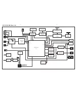
Страница 17: ...4 1 4 1 BLOCK DIAGRAM Main Unit ...
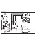
Страница 19: ...4 3 4 3 BLOCK DIAGRAM Subwoofer TI5342LA TI5342LA TI5342LA TI5342LA TAS5508 ...
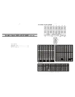
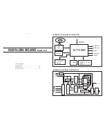
Страница 35: ...9 1 9 1 IPOD BOARD main unit TABLE OF CONTENTS Circuit Diagram 9 2 PCB Layout View 9 3 ...
Страница 51: ...13 1 REVISION LIST Version 1 0 Initial release ...


