3 - 3
3 - 3
SERVICE POSITIONS
Note:In some service positions the components or copper patterns of one board may risk touching its neighbouring pc boards or
metallic parts. To prevent such short-circuit use a piece of hard paper or other insulating material between them.
Dismantling of the POWER PCB
1) Loosen 4 screws “R” on the bottom of Power PCB as shown in fi gure 19.
R
Figure 19
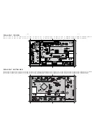
Service Position C – All Boards
Service Position B - AMP & Power Board
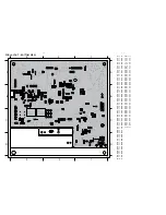
Service Position A - BD & MAIN Board
Содержание HTS5220
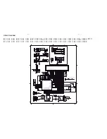
Страница 10: ...2 3 2 3 REPAIR INSTRUCTIONS One ...
Страница 11: ...2 4 2 4 REPAIR INSTRUCTIONS Two M8530 BD Board Repair Block Diagram ...
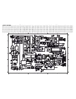
Страница 15: ...4 1 4 1 BLOCK DIAGRAM ...
Страница 17: ...5 1 5 1 QUICK START GUIDE User Manual SCART Converter Composite Speaker Cables 2 1 ...
Страница 36: ...10 1 10 1 TOUCH BOARD TABLE OF CONTENTS Circuit Diagram 10 2 PCB Layout Top View Bottom View 10 3 ...
Страница 40: ...11 2 11 2 Voltages for per connection pin ˠ ˣ ˢˠ ˢ ˢ ˢ ˢ ˢ ...


