Top Case Assembly
4
-
56
Removal and Replacement
Top Case Assembly
Description
The top case assembly consists of the following components, all pre assem-
bled into the case at the factory.
z
Display window.
z
IRDA and Ambient Light lenses.
z
Main Keypad subassembly.
z
Printer ribbon cable
Should the case itself or any one of these components sustain damage, the top
case assembly must be replaced.
Removal and replacement
The Top Case is probably the most difficult and time consuming repair that
can be done on the M3500B/M5500B. Some parts need to be moved from the
old case to the new; and new parts must be installed. Some of the new parts
come with the top case and some must be ordered separately.
Parts to be moved from old top case to new
The following subassemblies must be removed from the old top case and
installed into the new one. Follow the Removal and Replacement instructions
in this chapter for each subassembly. Remove them in the order shown, and
replace them in reverse order.
1. Printer (see "Printer Assembly" on page 4-11).
2. Manual door and label (see "Manual Door" on page 4-4).
3. Shaft and mounting rails for Manual Door ("Manual Keypad Assembly"
4. Control stack ("Control Stack" on page 4-33).
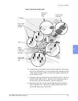
5. Interface PCA, with its ribbon cable and insulating shield (see "Interface
6. SpO
2
connector and flex circuit (if present) (see "SpO
7. ECG connector and cable with ferrite (see "ECG Connector" on page 4-
8. SpO
2
PCA (if present) and flex with ferrite (see "SpO2 PCA" on page 4-
38). The flex circuit and ferrite will be reused.
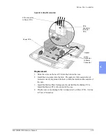
9. Speaker, hardware, tape (see "Speaker" on page 4-55).
10. All screws.
Содержание Heartstart XLT
Страница 1: ...H E A R T S TA R T X LT S e r v i c e M a n u a l M 3 5 0 0 B M 5 5 0 0 B ...
Страница 2: ......
Страница 3: ...Service Manual M3500B HeartStart XLT M5500B Heartstart 4000 Defibrillator Monitor ...
Страница 6: ......
Страница 16: ......
Страница 20: ......
Страница 52: ......
Страница 110: ...Opening the Sealed Case 4 24 Removal and Replacement Figure 4 13 Battery Connector Location 4 Pin Battery Connector ...
Страница 195: ...M3500B M5500B Service Manual 6 17 System Functional Descriptions 6 Figure 6 3 Power Distribution and Fusing ...
Страница 205: ...M3500B M5500B Service Manual 7 9 Waveforms 150J continued 7 Waveforms 150J continued 150J 75 ohms 150J 100 ohms ...
Страница 206: ...Waveforms 150J continued 7 10 Specifications Waveforms 150J continued 150J 125 ohms 2ms div 150J 125 ohms 5 ms div ...
Страница 208: ...Waveforms 200J continued 7 12 Specifications Waveforms 200J continued 200J 75ohms 200J 100ohms ...
Страница 216: ......
Страница 223: ......
Страница 224: ...M3500 90900 Printed in USA February 2003 Second Edition M3500 90900 2 ...


