


2-1
2-1
DISMANTLING INSTRUCTIONS
1) Loosen 4 screws to remove the Cover Top of the set.
2) Loosen 2 screws to remove the Panel Left and 2 screws
to remove the Panel Right of the set.
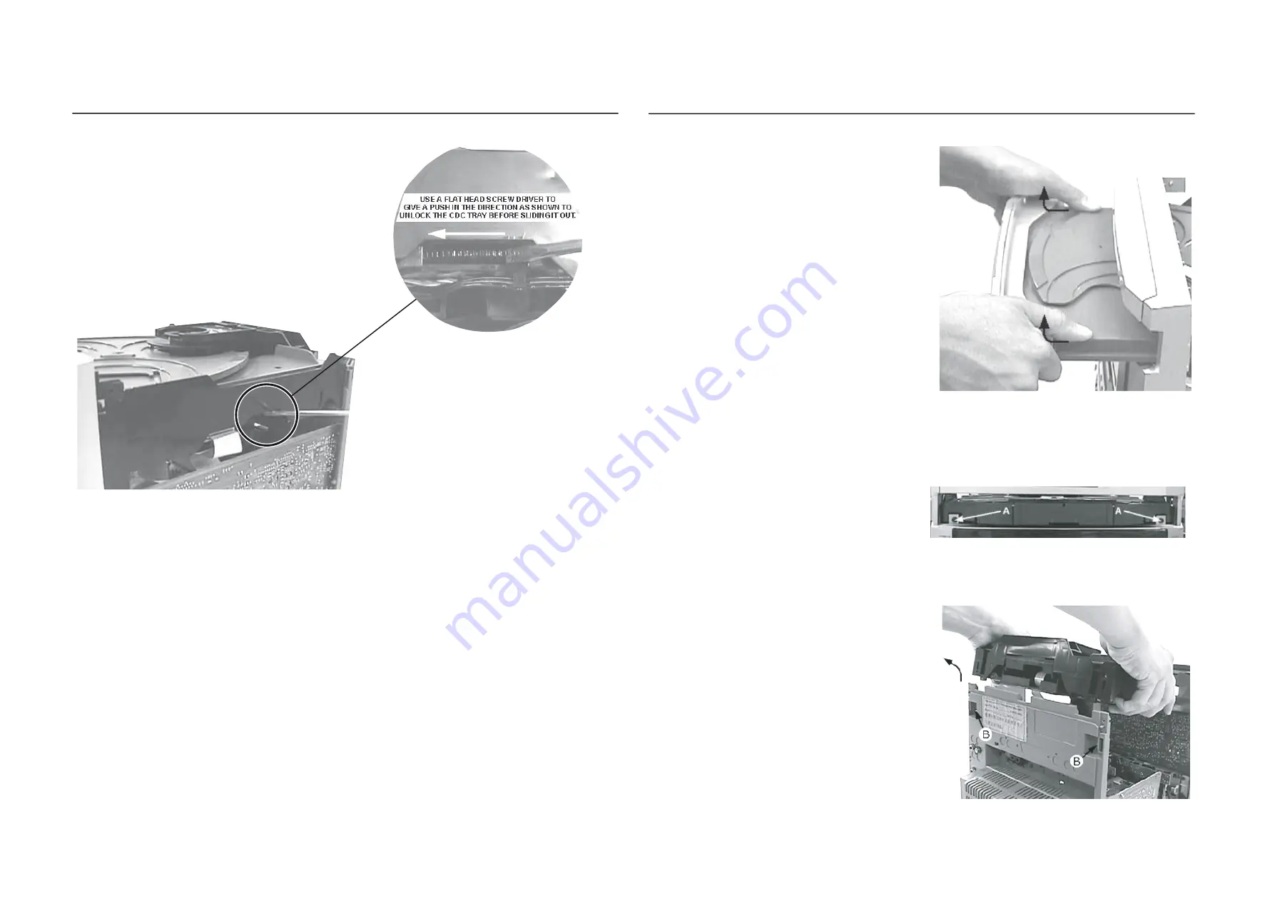
3) Slide out the CDC Tray as shown in the diagram below with
the help of a flat head screw driver.
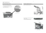
Dismantling of the CDC Module and Front Panel
Remove CDC Module
4) Remove the Cover Tray CDC as indicated.
Front View CDC
Remove Cover Tray CDC
Dismantling of the CDC Module and Front Panel
Sliding Out The CDC Tray
5) Loosen 2 screws A and 2 screws B to remove the CDC
Module as indicated.
6) Remove 2 screws at the bottom to separate the
Front Panel Assembly from the Plate Bottom .
Содержание FWM583
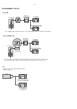
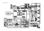
Страница 10: ...74HCT04D HEF4013BT 4 1 4 1 SET BLOCK DIAGRAM ...
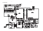
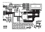
Страница 11: ...4 2 4 2 SET WIRING DIAGRAM ...
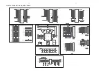
Страница 12: ...5 1 5 1 PCB LAYOUT FRONT BOARD TOP VIEW ...
Страница 13: ...5 2 5 2 PCB LAYOUT FRONT BOARD BOTTOM VIEW ...
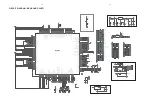
Страница 16: ...6 1 6 1 PCB LAYOUT MCU BOARD TOP VIEW ...
Страница 17: ...6 2 6 2 PCB LAYOUT MCU BOARD BOTTOM VIEW ...
Страница 20: ...9 1 9 1 LAYOUT DIAGRAM MAINS BOARD TOP VIEW ...
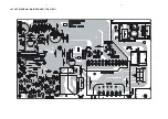
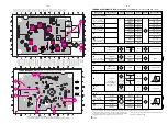
Страница 25: ...8 2 8 2 LAYOUT DIAGRAM CD BOARD TOP VIEW ...
Страница 26: ...8 3 8 3 LAYOUT DIAGRAM CD BOARD BOTTOM VIEW ...
Страница 29: ...9 1 9 1 LAYOUT DIAGRAM MAINS BOARD TOP VIEW ...
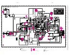
Страница 30: ...9 2 9 2 CIRCUIT DIAGRAM MAINS BOARD ...
Страница 31: ...9 3 9 3 LAYOUT DIAGRAM MIC BOARD TOP VIEW LAYOUT DIAGRAM MIC BOARD BOTTOM VIEW ...
Страница 33: ...10 1 10 1 LAYOUT DIAGRAM HIGH AMP USB JACK BOARD TOP VIEW ...
Страница 34: ...10 2 10 2 LAYOUT DIAGRAM HIGH AMP USB JACK BOARD BOTTOM VIEW ...
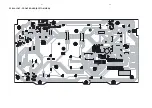
Страница 35: ...10 3 10 3 LAYOUT DIAGRAM POWER BOARD TOP VIEW ...
Страница 36: ...10 4 10 4 LAYOUT DIAGRAM POWER BOARD BOTTOM VIEW ...
Страница 37: ...CIRCUIT DIAGRAM HIGH AMP BOARD POWER BOARD 10 3 10 3 ...
Страница 41: ...12 4 12 4 SOURCE SELECTION SOUND PROCESSING CIRCUIT ...
Страница 42: ...12 5 12 5 HEADPHONE AMPLIFIER I2 C EXPANDER CIRCUIT 1K ...
Страница 44: ...SET MECHANICAL EXPLODED VIEW 13 1 13 1 ...


