


EN 147
3139 785 31150
9.
Circuit- and IC description
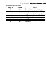
Reset concept Digital board
The voltage detector NCP303LSN29 [7106] provides the
reset signal PNX7100_RESETn with the correct timing
behavior. This circuitry functions as a Power-on reset module
which detects the minimum functional voltage that is needed
by the device. It also detects any voltage drop. When the
power voltage is outside the nominal range, a reset signal is
generated and fed to the Chrysalis chip to reset the differenct
peripherals and processing units.
•
PNX7100_RESETn = High {the Digital board is up and
running}
•
PNX7100_RESETn = Low {the Digital board will reset}
There are two control lines which can overrule this reset
signal:
•
IRESET_DIG (controlled by the microprocessor on the
Analog
Board)
•
EJTAG_RESETn (only for production)
The PNX7100_SYS_RESETn is a general enabling signal
for the different reset lines. All other reset lines are directly
driven from the Chrysalis port pins. All reset lines are logically
connected via 74LVC08AD [7104 and 7107] AND-gates. If both
reset signals are low, all other external devices are initialized.
9.5.8. In/Out
Connector
Audio In/Out Connector [1900]
The Audio In / Out (AIO) connector is used to interchange
digital audio signals between the Analog and Digital board.
Video In/Out Connector [1904]
The Video In / Out (VIO) Connector is used to interchange
analogue video signals between the Analog and Digital board.
Video Out Connector [1002] (Not for European version)
The Video Out Connector is used for Progressive Scan video
signals to the Analog board
9.5.9. Service UART Interface
Transistors 7004 and 7112 are used to make a level
conversion between LVTTL and 5V (compatible with most
RS232 interfaces) and vice versa. The control line MPIO19_
EEPROM_En is used to activate service and diagnostic
SW at start-up. The connectivity is provided via an external
service tool.
CHRYSALIS
PNX7100EH
7400
GPIO
PNX7100_RESETn
PNX7100_SYS_RESETn
7106
3V3
>1
EJTAG_RESETn
IRESET_DIG
NCP303
7104-2
&
7107-4
&
RESET_IDE1n
7107-3
&
RESET_1394n
7107-2
&
RESET_DTTMn
RESET_PROGSCANn
3V3_RES
7104-3
&
7107-1
&
ANALOG_RESETn
7104-1
&
VIP_RESETn
RESET_IDE2n
Figure 9-6 Reset concept
9.5.5. Power Supply
The Digital board is not powered in standby mode. The
control signal STBY on the analog board will enable the PSU
and power the digital board.
•
STBY = High : the digital board is in powered down
standby
mode
•
STBY = Low : the power supply to the digital board
is enabled. The 3V3, -5V, +5V and
+12V come from the PSU, while the
following voltages are generated in the
digital
board:
•
1.8V core voltage generated by a NCP1571D [7501] .
It provides a DC-DC power solution producing a 1.8V
output voltage over a wide current range
•
1.8V_VIP generated by LD1117D18 [7008] for the VIP
•
3.3V_VIP generated by LD1117D33 [7006] for the VIP
•
2.5V generated by a LF25CDT [7600] for Pro-scan Video
Encoder (Not for European set)
9.5.6. Memory
Several memories are used on the Digital Board:
•
Eeprom IC [7809] : this memory contains all the
parameters for the application
•
Eeprom IC [7810] : this memory contains the boot
parameters of the board
•
Flash IC [7807] : this memory contains the application
and Service diagnostic
fi
rmware
9.5.7. Reset
Содержание DVDR3330H/02
Страница 102: ...EN 102 3139 785 31150 Firmware Upgrading Diagnostic Software 5 Notes ...
Страница 138: ...EN 138 3139 785 31150 7 Circuit Diagrams and PWB Layouts Notes ...
Страница 156: ...EN 156 3139 785 31150 9 Circuit and IC Description PIN DESCRIPTION AND CONFIGURATION ...
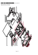
Страница 160: ...EN 160 3139 785 31150 910 901 910 910 Exploded View of the Set Figure 10 1 10 Service Parts List ...