


Static Center Convergence
Review Pre-Convergence Information
1. Connect a Center Cross pattern or a Crosshatch pattern to the Antenna input to ensure
that the yoke is not tilted. Rotate the yoke, if necessary, to obtain a level raster.
2. Use Service Page G to set the Green control to minimum.
3. Set the Blue control to its mid-range position.
4. Slowly spread and, if necessary, rotate the 4-Pole Magnetic Rings to converge Red
and Blue lines at the center of the screen.
5. Reset the Green Control to mid-range.
6. Slowly spread and, if necessary, rotate the 6-Pole Magnetic Rings to converge
Red/Blue on Green lines at the center of the screen.
7. Repeat the procedure for optimum performance.
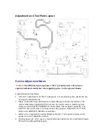
Dynamic Edge Convergence
Review Pre-Convergence Information
Note:
Three rubber wedges are used to secure the correct position of the Deflection Yoke They
are to ultimately be placed as shown in figure C or F of this display.
1. Apply a crosshatch pattern signal to the antenna input.
2. Use Service Page "G" to set the green control to minimum.
3. Tilt the Yoke Up and Down to converge the Red and Blue vertical lines at the 6 and
12 o'clock positions and the Red and Blue Horizontal lines at the 3 and 9 o'clock
positions
4. When the correct position has been found, place a rubber wedge between the Yoke
and the CRT. If the yoke is tilted UP, place wedge 1 as shown in Figure A. If the
Yoke is tilted DOWN, place wedge 1 as shown in Figure D.
5. Tilt the Yoke to the left and right to find the point of best possible convergence of the
Red and Blue lines at the edges, top and bottom of the screen.
Содержание B8 Series
Страница 2: ......
Страница 3: ......
Страница 4: ......
Страница 5: ......
Страница 6: ......
Страница 7: ......
Страница 8: ......
Страница 9: ......
Страница 10: ......
Страница 11: ......
Страница 14: ...20B8 7562 41 110 Vp p 20 uSec ...
Страница 19: ...All Models 7562 MAIN CHASSIS SECTION 1 OF 5 ...
Страница 20: ...All Models 7562 MAIN CHASSIS SECTION 2 OF 5 ...
Страница 21: ...All Models 7562 MAIN CHASSIS SECTION 3 OF 5 ...
Страница 22: ...All Models 7562 MAIN CHASSIS SECTION 4 OF 5 ...
Страница 23: ...All Models 7562 MAIN CHASSIS SECTION 5 OF 5 ...
Страница 24: ...All Models 7562 CRT PANEL 13 19 20 ...
Страница 25: ...All Models 7562 CRT PANEL 25 27 ...
Страница 26: ...All Models 7562 KEYBOARD SOUND SHAPER PANEL ...
Страница 27: ...All Models 7562 STEREO PANEL SCHEMATIC ...
Страница 28: ...All Models 7562 OCV TV PANEL SCHEMATIC ...
Страница 29: ...All Models 7562 CARD INTERCONNECT PANEL ...
Страница 30: ...All Models 7562 HEALTH CARE JACK PANEL ...
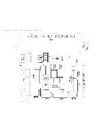
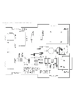
Страница 31: ...All Models 7562 LODGING SMART PORT PANEL ...
Страница 32: ...All Models 7562 MAIN CHASSIS PCB TOP ...
Страница 33: ...All Models 7562 MAIN CHASSIS PCB BOTTOM ...
Страница 34: ...All Models 7562 13 19 20 CRT PANEL PCB ...
Страница 35: ...All Models 7562 25 27 CRT PANEL PCB ...
Страница 36: ...All Models 7562 KEYBOARD SOUND SHAPER PCB ...
Страница 37: ...All Models 7562 STEREO PANEL PCB ...
Страница 38: ...All Models 7562 OCV TV PANEL PCB TOP ...
Страница 39: ...All Models 7562 OCV TV PANEL PCB BOTTOM ...
Страница 40: ...All Models 7562 CARD INTERCONNECT PANEL PCB ...
Страница 41: ...All Models 7562 HEALTH CARE JACK PANEL PCB ...
Страница 42: ...All Models 7562 LODGING SMART PORT PANEL PCB ...


