


Focus
1. Tune to a local station and adjust the Focus Control (located on the Flyback
Transformer) for best picture details at high light conditions.
Screen Control (G2) Setup (13", 19", & 20")
1. Apply an NTSC Color Bar test pattern, with the color "off", to the antenna input of
the TV Receiver.
2. Select the active channel.
3. Set all the customer picture controls to mid-range.
4. Using an oscilloscope measure and note the peak to peak voltage of the CRT
Cathodes. Use the legs of R11, R12, and R13 which tie to the CRT socket.
5. Using the cathode with the highest peak to peak voltage, noted in step 4, adjust the
Screen Voltage (G2) control (located on the Flyback Transformer) to obtain 120Vp-p.
Screen Control (G2) Setup (25" & 27")
1. Apply an NTSC Color Bar test pattern, with the color "off", to the antenna input of
the TV Receiver.
2. Select the active channel.
3. Set all the customer picture controls to mid-range.
4. Using an oscilloscope measure and note the peak to peak voltage of the CRT
Cathodes. Use the legs of R60, R61, and R62 which tie to the CRT socket.
5. Using the cathode with the highest peak to peak voltage, noted in step 4, adjust the
Screen Voltage (G2) control (located on the Flyback Transformer) to obtain 120Vp-p.
Adjusting The Picture
Note: The Color Purity and Convergence Adjustments described below should be performed
only after installation of a new CRT or Deflection Yoke Assembly otherwise, it will not
be necessary to remove the rubber wedges. Minor corrections for purity and convergence
Содержание B8 Series
Страница 2: ......
Страница 3: ......
Страница 4: ......
Страница 5: ......
Страница 6: ......
Страница 7: ......
Страница 8: ......
Страница 9: ......
Страница 10: ......
Страница 11: ......
Страница 14: ...20B8 7562 41 110 Vp p 20 uSec ...
Страница 19: ...All Models 7562 MAIN CHASSIS SECTION 1 OF 5 ...
Страница 20: ...All Models 7562 MAIN CHASSIS SECTION 2 OF 5 ...
Страница 21: ...All Models 7562 MAIN CHASSIS SECTION 3 OF 5 ...
Страница 22: ...All Models 7562 MAIN CHASSIS SECTION 4 OF 5 ...
Страница 23: ...All Models 7562 MAIN CHASSIS SECTION 5 OF 5 ...
Страница 24: ...All Models 7562 CRT PANEL 13 19 20 ...
Страница 25: ...All Models 7562 CRT PANEL 25 27 ...
Страница 26: ...All Models 7562 KEYBOARD SOUND SHAPER PANEL ...
Страница 27: ...All Models 7562 STEREO PANEL SCHEMATIC ...
Страница 28: ...All Models 7562 OCV TV PANEL SCHEMATIC ...
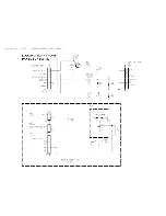
Страница 29: ...All Models 7562 CARD INTERCONNECT PANEL ...
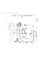
Страница 30: ...All Models 7562 HEALTH CARE JACK PANEL ...
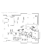
Страница 31: ...All Models 7562 LODGING SMART PORT PANEL ...
Страница 32: ...All Models 7562 MAIN CHASSIS PCB TOP ...
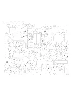
Страница 33: ...All Models 7562 MAIN CHASSIS PCB BOTTOM ...
Страница 34: ...All Models 7562 13 19 20 CRT PANEL PCB ...
Страница 35: ...All Models 7562 25 27 CRT PANEL PCB ...
Страница 36: ...All Models 7562 KEYBOARD SOUND SHAPER PCB ...
Страница 37: ...All Models 7562 STEREO PANEL PCB ...
Страница 38: ...All Models 7562 OCV TV PANEL PCB TOP ...
Страница 39: ...All Models 7562 OCV TV PANEL PCB BOTTOM ...
Страница 40: ...All Models 7562 CARD INTERCONNECT PANEL PCB ...
Страница 41: ...All Models 7562 HEALTH CARE JACK PANEL PCB ...
Страница 42: ...All Models 7562 LODGING SMART PORT PANEL PCB ...


