b
P
b
P
24
AV4
SIDE
AV2
CVI
AV1
AUDIO OUT
R L
S-VIDEO
OUT
ANT/CABLE
OUT
VIDEO
OUT
1
3
4
5
7
2
PIP ON/OFF
2
1
3
5
4
6
8
7
9
0
TV
SWAP
PIP CH
DN
UP
ACTIVE
CONTROL FREEZE
SOUND
MUTE
SURF
A/CH
POWER
PICTURE
STATUS/
EXIT
SURF
ITR/
RECORD
HOME
VIDEO
HOME
MOVIES
PERSONAL
SLEEP
REC •
PIP
POSITION
VCR
ACC
MENU/
SELECT
VOL
CH
TV/VCR
CC
SAP
PROG.LIST
DOLBY V
AV
6
7
T
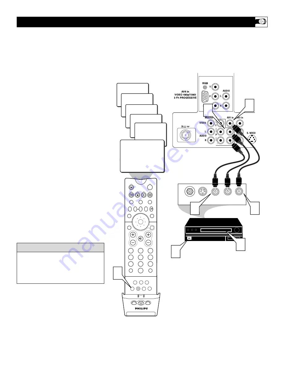
he TV’s audio/video input jacks are for
direct picture and sound connections
between the TV and a VCR (or similar device)
that has audio/video output jacks. Follow the
easy steps below to connect your accessory
device to the AV 1 Input Jacks located on the
back of the TV.
1
Connect the VIDEO (yellow) cable
to
the VIDEO AV1 in jack on the back of
the TV.
2
Connect the AUDIO (red and white)
cables
to the AUDIO (left and right)
AV1 in jacks on the rear of the TV.
3
Connect the VIDEO (yellow) cable
to
the VIDEO OUT jack on the back of
the VCR.
4
Connect the AUDIO (red and white)
cables
to the AUDIO (left and right)
OUT jacks on the rear of the VCR.
5
Turn the VCR (accessory device) and
the TV ON.
6
Press the AV button
on the remote
control to select the AV1 channel. AV1
will appear in the upper left corner on
the TV screen.
7
With the VCR (or accessory device)
ON and a prerecorded tape (CD, DVD,
etc.) inserted,
press the PLAY button
to view the tape on the television.
U
SING THE
AV 1 I
NPUT
J
ACKS
Repeatedly pressing the AV button on the
remote control will toggle the picture source
from the current channel, then AV1, CVI,
AV2, SIDE (AV3), and the AV4 Input Jack
connections.
c
c
C
HECK
I
T
O
UT
AUDIO IN
(RED/WHITE)
VCR
(EQUIPPED WITH VIDEO AND
AUDIO OUTPUT JACKS)
VIDEO IN
(YELLOW)
BACK OF VCR
NOTE:
Repeatedly pressing the AV button on the remote control will toggle the
picture source from the current channel, the AV1 channel, then the CVI channel,
then the AV2 channel, then the SIDE (AV3) channel and the AV4 channel. After the
AV4 channel, the AV button will select the current channel again.
BACK OF TV


