ComPair
Introduction
ComPair (Computer Aided Repair) is a service tool for Philips Consumer Electronics products.
ComPair is a further development on the European DST (service remote control), which allows
faster and more accurate diagnostics. ComPair has three big advantages:
ComPair helps you to quickly get an understanding on how to repair the chassis in a short
time by guiding you systematically through the repair procedures.
ComPair allows very detailed diagnostics (on I2C level) and is therefore capable of
accurately indicating problem areas. You do not have to know anything about I2C
commands yourself because ComPair takes care of this.
ComPair speeds up the repair time since it can automatically communicate with the chassis
(when the microprocessor is working) and all repair information is directly available. When
ComPair is installed together with the Force electronic manual of the defective chassis,
schematics and PWBs are only a mouse click away.
Specifications
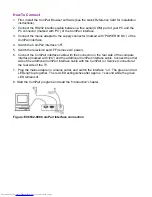
ComPair consists of a Windows based faultfinding program and an interface box between PC
and the (defective) product. The ComPair interface box is connected to the PC via a serial or
RS232 cable.
In this chassis, the ComPair interface box and the TV communicate via a bi-directional service
cable via the service connector.
The ComPair faultfinding program is able to determine the problem of the defective television.
ComPair can gather diagnostic information in two ways:
l
Automatic
(by communication with the television): ComPair can automatically read out the
contents of the entire error buffer. Diagnosis is done on I2C level. ComPair can access the
I2C bus of the television. ComPair can send and receive I2C commands to the micro
controller of the television. In this way, it is possible for ComPair to communicate (read and
write) to devices on the I2C busses of the TV-set.
l
Manually
(by asking questions to you): Automatic diagnosis is only possible if the micro
controller of the television is working correctly and only to a certain extend. When this is not
the case, ComPair will guide you through the faultfinding tree by asking you questions (e.g.
Does the screen give a picture? Click on the correct answer: YES / NO)
and showing you
examples (e.g.
Measure test-point I7 and click on the correct waveform you see on the
oscilloscope)
. You can answer by clicking on a link (e.g., text or a waveform picture) that will
bring you to the next step in the faultfinding process.
By a combination of automatic diagnostics and an interactive question / answer procedure,
ComPair will enable you to find most problems in a fast and effective way.
Содержание 26FW5220
Страница 1: ......
Страница 5: ......
Страница 39: ...SAM Menu Figure E14490 054 SAM Menu nieuw nummer ...
Страница 44: ...LC4 2U AA 7670 F302 F303 F306 I341 I344 F701 F702 F705 F706 F707 F708 I904 F452 F613 F615 F617 F624 F625 F626 ...
Страница 45: ...All Models 7670 Chassis Overview ...
Страница 46: ...All Models 7670 Power Supply A1 ...
Страница 47: ...All Models 7670 Hercules A2 ...
Страница 48: ...All Models 7670 Histogram A3 ...
Страница 49: ...All Models 7670 Audio Amplifier A5 ...
Страница 50: ...All Models 7670 TV Supply A6 ...
Страница 51: ...All Models 7670 Scaler A7 ...
Страница 52: ...All Models 7670 Scaler Interface A9 ...
Страница 53: ...All Models 7670 SDRAM A10 ...
Страница 54: ...All Models 7670 Flash Control A11 ...
Страница 55: ...All Models 7670 HDMI A12 ...
Страница 56: ...All Models 7670 PCHD MUX A13 ...
Страница 57: ...All Models 7670 Supply A14 ...
Страница 58: ...All Models 7670 3D Comb Filter CB ...
Страница 59: ...All Models 7670 Side IO and LKB Panel D ...
Страница 60: ...All Models 7670 Cinch 17 H1 ...
Страница 61: ...All Models 7670 PCHD IO 17 H2 ...
Страница 62: ...All Models 7670 Rear IO Cinch 23 26 H1 ...
Страница 63: ...All Models 7670 PCHD IO 23 26 H2 ...
Страница 64: ...All Models 7670 Front IR LED Panel J ...
Страница 65: ...All Models 7670 EPLD Control PP1 ...
Страница 66: ...All Models 7670 LVDS In PP2 ...
Страница 67: ...All Models 7670 EPLD I O PP3 ...
Страница 68: ...All Models 7670 Power Supply PP4 ...
Страница 69: ...All Models 7670 Layout Tv Scaler Board Overview Top Side ...
Страница 70: ...All Models 7670 Layout Tv Scaler Board Overview Bottom Side ...
Страница 71: ...All Models 7670 Layout 3D Comb Filter Top Side ...
Страница 72: ...All Models 7670 Layout 3D Comb Filter Bottom Side ...
Страница 73: ...All Models 7670 Layout Side IO and LKB Panel Top Side ...
Страница 74: ...All Models 7670 Layout Side IO and LKB Panel Bottom Side ...
Страница 75: ...All Models 7670 Layout Rear IO Panel 17 Top Side ...
Страница 76: ...All Models 7670 Layout Rear IO Panel 17 Bottom Side ...
Страница 77: ...All Models 7670 Layout Rear IO Panel 23 26 Top Side ...
Страница 78: ...All Models 7670 Layout Rear IO Panel 23 26 Bottom Side ...
Страница 79: ...All Models 7670 Layout Front IR LED Panel Top Side ...
Страница 80: ...All Models 7670 Layout Front IR LED Panel Bottom Side ...
Страница 81: ...All Models 7670 Layout Pixel Plus Panel Top Side ...
Страница 82: ...All Models 7670 Layout Pixel Plus Panel Bottom Side ...
Страница 83: ...All Models 7670 Testpoint Overview TV Scaler Board Bottom Side ...
Страница 84: ...All Models 7670 Testpoint Overview TV Scaler Board Top Side ...
Страница 85: ...All Models 7670 Wiring Diagram ...
Страница 86: ...All Models 7670 Block Diagram Tuner and IF Video ...
Страница 87: ...All Models 7670 Block Diagram Scaler ...
Страница 88: ...All Models 7670 I2C IC Overview ...
Страница 89: ...All Models 7670 Supply Voltage Overview ...
Страница 109: ...Diagram A7 Type GM1501 IC7401 Figure Internal Block Diagram and Pin Configuration ...
Страница 110: ...Diagram A12 Type S9993CT IC7808 Figure Internal Block Diagram ...


