Alignments
8.
8.
Alignments
Index of this chapter
8.1 Electrical Instructions
8.2 Serial Number Definition (3rd character)
Note:
The Service Alignment Mode is described in chapter 5.
Menu navigation is done with the CURSOR UP, DOWN, LEFT
or RIGHT keys of the remote control transmitter.
8.1
Electrical Instructions
8.1.1
EXT3 YPbPr Mode Display Adjustment
Requirements
Equipment requirements:
- Minolta CA-110 or CA-210 or equivalent colour analyser.
- Quantum Data pattern generator 802G, 802BT, 881 or
equivalent instrument.
Input requirements:
Input signal type: YPbPr signal
1.
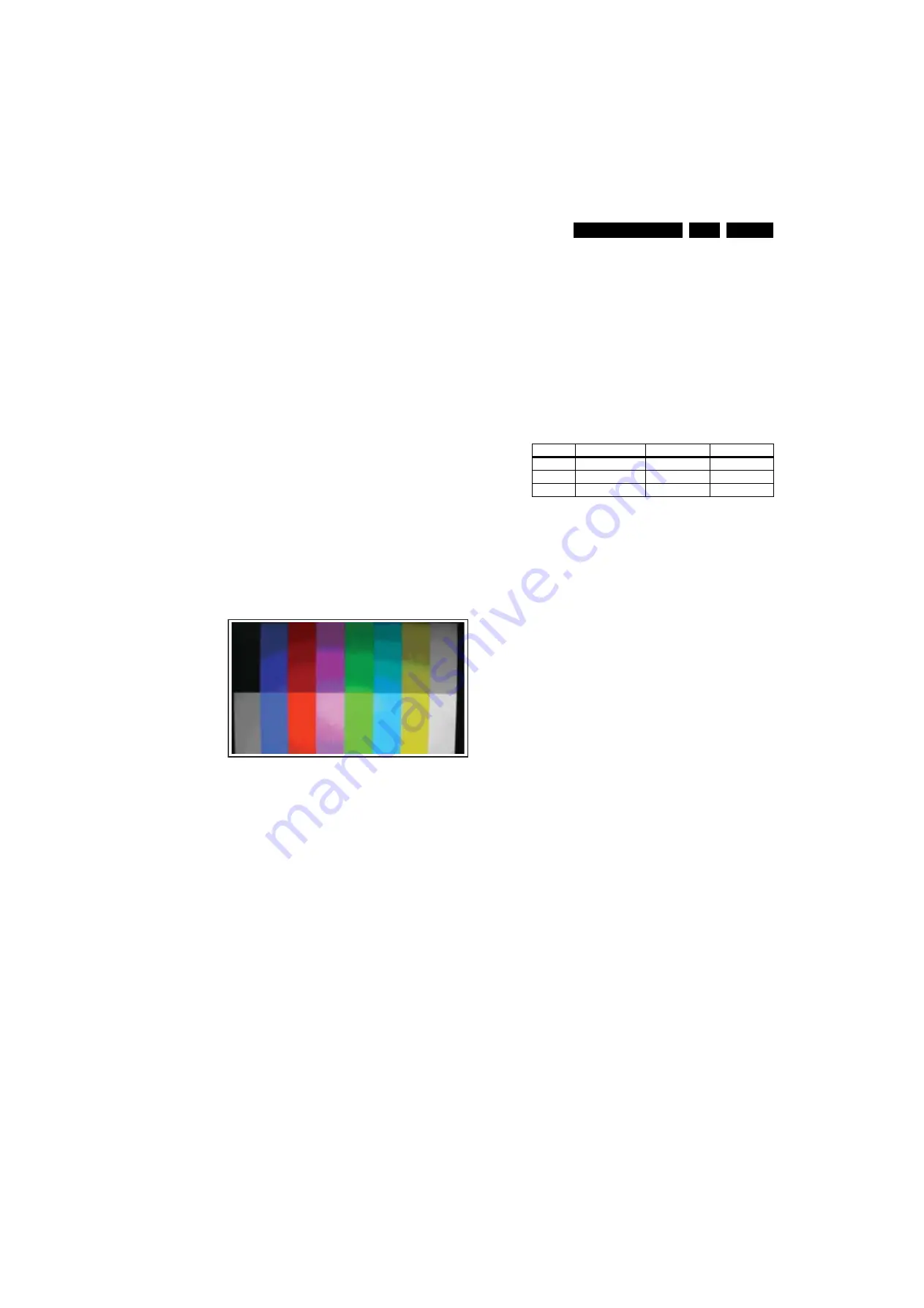
1080i mode, TVBar100 pattern by 802G or 802BT or 881.
2.
Set “Smart Picture” to “Personal” mode and check the
x, y data.
Input Signal Strength: 1000 mVpp for Y signal; +/- 350 mV for
Pb & Pr signal.
Input Injection Point: EXT3 YPbPr (RAC jack) 1080i, TVBar100
pattern.
Figure 8-1 Pattern 27
Alignment method:
1.
Select source as "EXT3".
2.
Set Smart picture as "Personal" and Contrast=50,
Brightness=50, Color=50.
3.
Apply "SMPTE color" pattern or "color bar with black &
white" pattern by signal generator.
4.
Enter factory mode menu: press numeric keys "062596" +
"INFO" key+ "MENU" key (FAC mode menu). Then select
"Factory" item.
Alignment
1.
In “FACTORY” mode menu, select AUTO_COLOR item.
Then press the "OK" key to auto adjust ADC_GAIN_R,
ADC_GAIN_G, ADC_GAIN_B and ADC_OFFSET_R,
ADC_OFFSET_G, ADC_OFFSET_B. Then “STORE”
those values to NVM.
2.
Apply full white pattern.
3.
Set “Color Temperature” to "NORMAL".
4.
In “FACTORY” mode menu, keep the CLR_TEMP_B=128,
and adjust the CLR_TEMP_G, CLR_TEMP_R values to
meet the "NORMAL" colour coordinates as specified
below. Then “STORE” those values to NVM.
5.
Set “Color Temperature” to "WARM".
6.
In “FACTORY” mode menu, keep the CLR_TEMP_R=128,
and adjust the CLR_TEMP_G, CLR_TEMP_B values to
meet the "WARM" colour coordinates specified below.
Then “STORE” those values to NVM.
7.
Set “Color Temperature” to "COOL".
8.
In “FACTORY” mode menu, keep the CLR_TEMP_B=128,
and adjust the CLR_TEMP_G, CLR_TEMP_R values to
meet the "COOL" colour coordinates specified below. Then
“STORE” those values to NVM.
Output detection point: screen center.
Table 8-1 Check (x,y) cooridiates as belows
8.1.2
PC Mode Adjustment
White balance Adjustment (B)
Equipment Requirements:
- Minolta CA-110 or CA-210 or equivalent colour analyser
- Chroma 2250 or equivalent PC signal generator
Input requirements:
Input Signal Type: PC VGA signal
1.
1024x768@60Hz PC mode with 5 white block pattern.
(see the next figures)
2.
Select “Colour Temperature” to “Normal”, and check the
x, y data.
Input signal strength: 0.7 Vpp linear voltage.
Input injection point: PC D-SUB input.
Settings
1.
Select source as "PC".
2.
Set Contrast= 50, Brightness= 50, set “Color Temperature”
as “Normal” and set “Picture Format” as “Full Screen”.
3.
Apply "5 white block" pattern by VGA generator.
Alignment:
1.
In “FACTORY” mode menu, select AUTO_COLOR item.
Then press the "OK" key to auto adjust ADC_GAIN_R,
ADC_GAIN_G, ADC_GAIN_B and ADC_OFFSET_R,
ADC_OFFSET_G, ADC_OFFSET_B. Then “STORE”
those values to NVM.
2.
Set “Color Temperature” to "NORMAL".
3.
In “FACTORY” mode menu, keep the CLR_TEMP_B=128,
and adjust the CLR_TEMP_G, CLR_TEMP_R values to
meet "NORMAL" color coordinates specification above.
Then “STORE” those values to NVM.
4.
Set “Color Temperature” to "WARM".
5.
In “FACTORY” mode menu, keep the CLR_TEMP_R=128,
and adjust the CLR_TEMP_G, CLR_TEMP_B values to
meet "WARM" color coordinates specification above. Then
“STORE” those values to NVM.
6.
Set “Color Temperature” to "COOL".
7.
In “FACTORY” mode menu, keep the CLR_TEMP_B=128,
and adjust the CLR_TEMP_G, CLR_TEMP_R values to
meet "COOL" color coordinates specification above. Then
“STORE” those values to NVM.
Check gray scale
Check the color poor & noise condition of a 32 gray scale
pattern.
I_17550_012.ep
s
1
3
020
8
Normal (7200K) Warm (6300K) Cool (10500K)
x (center) 0.304
±
0.015
0.315
±
0.015
0.283
±
0.015
y (center) 0.312
±
0.015
0.323
±
0.015
0.283
±
0.015
Y (center) > 230
> 230
> 230
Содержание 22HFL3330D/10
Страница 14: ...Service Modes Error Codes and Fault Finding EN 14 TPM1 3HE LA 5 Personal Notes E_06532_012 eps 131004 ...
Страница 58: ...58 TPM1 3HE LA 7 Circuit Diagrams and PWB Layouts 3340D 10 Layout Scaler Board Top Side I_18121_020 eps 051108 ...
Страница 78: ...Revision List EN 78 TPM1 3HE LA 11 ...


