74
TPM1.0U LA
8. Alignments
Alignment method:
Initial Set-up
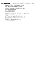
: Set Smart picture as "Personal", Brightness=50, Color=50, Contrast=50)
Then run factory " AUTO-COLOR "process.
Alignments
: Color temperature Normal/Warm/Cool DAC dada same as TV mode.
Check chromaticity (X, Y) co-ordinates specification:
If out of specification then fine-tune factory " ADC_GAIN_R / ADC_GAIN_R /
ADC_GAIN_R "
8.1.4
AV-2 (CVBS/S-V) mode display adjustment
8.1.4.1
White balance adjustment (B)
General set-up
: Use FLUKE 54200, CVBS and S-V with full white pattern in 100 IRE
output level.
Alignment method:
Initial Set-up
: Set Smart picture as "Personal", Brightness=50, Color=50, Contrast=50)
Alignments
: Color temperature Normal/Warm/Cool DAC dada same as TV mode.
Check chromaticity (X, Y) co-ordinates specification:
If out of specification then fine-tune factory "CLR_TEMP_R / CLR_TEMP_R /
CLR_TEMP_R "
8.1.5
HDMI mode adjustment and HDCP key
8.1.5.1 White balance adjustment (B)
General set-up : Quantum 802BT or equivalent equipments
Alignment method:
Initial Set-up
: Set Smart picture as "Personal", Brightness=50, Color=50, Contrast=50)
Alignments
: Color temperature Normal/Warm/Cool DAC dada same as TV mode.
Check chromaticity (X, Y) co-ordinates specification:
If out of specification then fine-tune factory " CLR_TEMP_R / CLR_TEMP_R /
CLR_TEMP_R "
Normal/ (8500
°
K)
Cool/(11500
°
K)
Warm/(6500
°
K)
x (center)
0.291
±
0.005
0.273
±
0.005
0.314
±
0.005
y (center)
0.302
±
0.005
0.280
±
0.005
0.324
±
0.005
Normal/ (8500
°
K)
Cool/(11500
°
K)
Warm/(6500
°
K)
x (center)
0.291
±
0.005
0.273
±
0.005
0.314
±
0.005
y (center)
0.302
±
0.005
0.280
±
0.005
0.324
±
0.005
Normal/ (8500
°
K)
Cool/(11500
°
K)
Warm/(6500
°
K)
x (center)
0.291
±
0.005
0.273
±
0.005
0.314
±
0.005
y (center)
0.302
±
0.005
0.280
±
0.005
0.324
±
0.005
8.1.5.2
HDCP Key Test (B)
8.1.5.2.1 Use pattern generator
Equipment: Quantum 802BT or equivalent equipments.
Pattern : Standard HDCP Pattern (It’s color bar)
Timing .
720 X 480P /60Hz
1280X 720P /60Hz
1920X1080i /60Hz
Result: The PASS information should be shown on the screen.
Содержание 19PFL5402D/27
Страница 2: ......
Страница 43: ...41 TPM1 0U LA 7 Circuit Diagrams and PWB Layouts Scaler Board Layout Top Side Part 1 ...
Страница 44: ...42 TPM1 0U LA 7 Circuit Diagrams and PWB Layouts Scaler Board Layout Top Side Part 2 ...
Страница 45: ...43 TPM1 0U LA 7 Circuit Diagrams and PWB Layouts Scaler Board Layout Top Side Part 3 ...
Страница 46: ...44 TPM1 0U LA 7 Circuit Diagrams and PWB Layouts Scaler Board Layout Top Side Part 4 ...
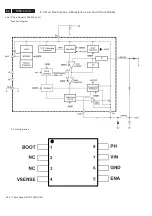
Страница 88: ...PIN ASSIGNMENT MT5372 MT5371 9 Circuit Descriptions Abbreviations List and IC Data Sheets 86 TPM1 0U LA ...
Страница 89: ...10 31 TPM1 0U LA 87 9 Circuit Descriptions Abbreviations List and IC Data Sheets ...
Страница 141: ...39 TPM1 0U LA 7 Circuit Diagrams and PWB Layouts Scaler Board Layout ...
Страница 142: ...40 TPM1 0U LA 7 Circuit Diagrams and PWB Layouts Scaler Board Layout TOP LEFT ...
Страница 143: ...41 TPM1 0U LA 7 Circuit Diagrams and PWB Layouts Scaler Board Layout TOP RIGHT ...
Страница 144: ...42 TPM1 0U LA 7 Circuit Diagrams and PWB Layouts Scaler Board Layout BUTTOM LEFT ...
Страница 145: ...43 TPM1 0U LA 7 Circuit Diagrams and PWB Layouts Scaler Board Layout BUTTOM RIGHT ...
Страница 146: ...44 TPM1 0U LA 7 Circuit Diagrams and PWB Layouts Scaler Board Layout 2 ...
Страница 147: ...45 TPM1 0U LA 7 Circuit Diagrams and PWB Layouts Scaler Board Layout 2 TOP LEFT ...
Страница 148: ...46 TPM1 0U LA 7 Circuit Diagrams and PWB Layouts Scaler Board Layout 2 TOP RIGHT ...
Страница 149: ...47 TPM1 0U LA 7 Circuit Diagrams and PWB Layouts Scaler Board Layout 2 BUTTOM LEFT ...
Страница 150: ...48 TPM1 0U LA 7 Circuit Diagrams and PWB Layouts Scaler Board Layout 2 BUTTOM RIGHT ...
Страница 190: ...PIN ASSIGNMENT MT5372 MT5371 88 TPM1 0U LA 9 Circuit Descriptions Abbreviations List and IC Data Sheets ...
Страница 191: ...89 TPM1 0U LA 9 Circuit Descriptions Abbreviations List and IC Data Sheets ...


