background image

4

Installation

107T6 CRT

Go to cover page

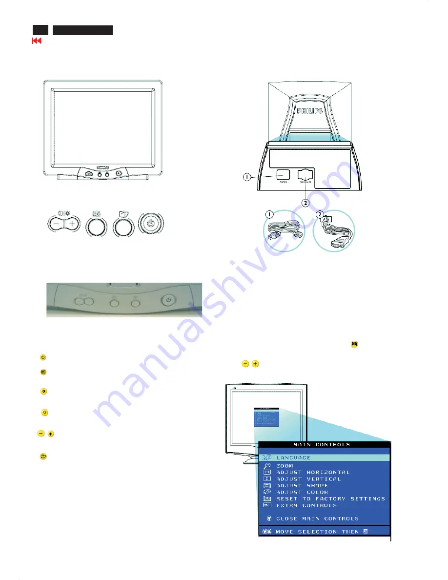
Power button switches your monitor.

OK button which when pressed will take you to the

OSD controls

Contrast hotkey. When the"-" button is pressed,the adjustment

controls for the CONTRAST will show up.

Brightness hotkey. When the "+" button is pressed,

the adjustment controls for BRIGHTNESS will show up.

"-" and "+" buttons, are used for adjusting the OSD of

your monitor.

LightFrame hotkey. When the button is pressed, the

adjustment controls for LightFrame will show up.

1. Power in-attach power cable here.

2. Video In-this is a cable which is already attached to your monitor.

Connect the other end of the cable to your PC.

This is a feature in all philips monitors which allows an end-user to

adjust screen performance of monitors directly through an on screen

instruction on window. The user interface provides user-friendliness and

ease-of-use when operating the monitor.

On the front controls of your monitor, once you press

button, the

On Screen Display (OSD) Main Controls window will pop up and you

can now start making adjustments to your monitor's various features.

Use the

buttons to make your adjustments within.

Description of the On Screen Display

What is the On Screen Display?

Basic and simple instruction on the control keys.

Front control

Rear View

Front View

Содержание 107T6

Страница 1: ...B A 38 40 44 Exploded View 45 48 55 86 93 LightFrame for Windows Control Diagram C B A 41 Waveform Diagram 42 Spare Parts List 46 Recommended Parts List 49 Different Parts List 50 Brief Circuit Description 52 General Product Specification 56 Repair Flow Chart 87 51 94 97 Repair Tips 98 Safety Test Requirements 99 REFER TO BACK COVER FOR IMPORTANT SAFETY GUIDELINES CAUTION USE A SEPARATE ISOLATION ...

Страница 2: ...nt will be jeopardized by the service method selected Hereafter throughout this manual Philips Consumer Electronics Company will be referred to as Philips Critical components having special safety characteristics are identified with a by the Ref No in the parts list and enclosed within a broken line where several critical components are grouped in one area along with the safety symbol on the schem...

Страница 3: ...CL 8 Blue video ground Automatic Power Saving If you have VESA DPMS compliance display card or software installed in your PC the monitor can automatically reduce its power consumption when not in use If an input from a keyboard mouse or other input device is detected the monitor will wake up automatically The following table shows the power consumption and signaling of this automatic power saving ...

Страница 4: ... is a cable which is already attached to your monitor Connect the other end of the cable to your PC This is a feature in all philips monitors which allows an end user to adjust screen performance of monitors directly through an on screen instruction on window The user interface provides user friendliness and ease of use when operating the monitor On the front controls of your monitor once you pres...

Страница 5: ...n and on the picture tube panel It is recommended that saferty goggles be worn when replacing the picture tube When making adjustments use plastic rather than metal tools This will prevent any short circuit or the danger of a circuit becoming unstable Never replace modules or other components while the unit is switched on Together with the defleciton unit the picture tube is used as an integrated ...

Страница 6: ...able is properly connected to your computer Check to see if the monitor cable has bent pins Make sure the computer Power button is on Make sure the monitor cable is properly connected to your computer Check to see if the monitor cable has bent pins Make sure the computer is turned on If you are using a non VESA DDC standard video card turn the DDC1 2B feature Off The picture may need degaussing Re...

Страница 7: ...he rear cover in Fig 1 and Fig 2 Remove 2 screws as shown Remove back cover as shown Remove pedestal as shown 2 Video panel Disconnect the wire between metal shield of video panel and CRT neck as shown in Fig 3 Disconnect the CRT grounding from Video panel Remove screw grounding and grounding wire in Fig 4 3 Main board connector in Fig 5 Disconnect york wire Disconnect rotation connector Disconnec...

Страница 8: ...TION Pull up Fig 8 4 Main panel with Bottom Tray Remove 2 screws for disconnect the Bottom tray as Fig 6 Remove the bottom tray on press right and left side clip from fig 7 to fig 8 5 SERVICE POSITION reconnect connectors some wires and panels chassis service position can be available for DC AC measurement as shown in Fig 9 ...

Страница 9: ...Go to cover page Electrical Instructions 107T6 CRT 9 ...

Страница 10: ...30 60 120 80 Sub contrast Sub contrast allowance range 220 220 200 220 Sub brightness Sub brightness allowance range 140 200 120 100 Sub H size adjustment range Fh 40KHz 185 220 185 220 40KHz Fh 55KHz 130 180 130 150 55KHz Fh 62KHZ 90 130 90 120 Sub H size Fh 62KHz 40 75 40 75 Fh 33KHz 90 100 82 42 33KHz Fh 36KHz 105 115 90 45 36KHz Fh 40KHz 110 128 98 50 40KHz Fh 44 KHz 115 130 110 55 44KHz Fh 47...

Страница 11: ...Go to cover page Electrical Instructions 107T6 CRT 11 ...

Страница 12: ...ontrast 3 When the contrast is adjusted to the level desired stop pressing the or button and after three seconds the CONTRAST window will disappear with the new adjustment saved Smart Help After the CONTRAST window has disappeared to continue to the MAIN CONTROLS follow the steps under LANGUAGE LANGUAGE The ON SCREEN DISPLAY shows its setting in one of eight languages The default is English but yo...

Страница 13: ...DJUST HORIZONTAL window appears ADJUST POSITION should be highlighted 4 Press the or button to move the image to the left or right 5 When the position is adjusted press the button to return to MAIN CONTROLS window or press the to highlight ADJUST SIZE 6 To adjust the horizontal size press the or button 7 When the size is adjusted press the button to return to MAIN CONTROLS window CLOSE MAIN CONTRO...

Страница 14: ...APE window appears ADJUST SIDE CURVE should be highlighted ADJUST SHAPE 4 Press the button The SIDE CURVE window appears PINCUSHION should be highlighted 5 To adjust the pincushion press the or button then press the button to save your selection 6 When the pincushion is adjusted press the button to highlight BALANCE or press the button to return to the ADJUST SHAPE window 7 To adjust the balanced ...

Страница 15: ...e button to return to the MAIN CONTROLS window or press the button until ROTATE IMAGE is highlighted Smart Help After returning to MAIN CONTROLS To continue to ROTATE IMAGE start with step 5 under ROTATE IMAGE and follow the directions To exit a completely press the button twice To adjust only the PARALLELOGRAM follow steps 1 4 above then press the button and follow steps 7 9 ROTATE IMAGE under AD...

Страница 16: ... button until ADJUST COLOR is highlighted 3 Press the button The ADJUST COLOR window appears 4 Press the or button to highlight 9300K for GENERAL USE 6500K for GAMES or USER PRESET 5 Once you have highlighted the GENERAL USE OR GAMES press the button to confirm your selection and return to the MAIN CONTROLS window CLOSE MAIN CONTROLS will be highlighted 6 If USER PRESET is highlighted press the bu...

Страница 17: ...s highlighted EXTRA CONTROLS 3 Press the button The EXTRA CONTROLS window appears ADJUST MOIRE will be highlighted 4 Press the button The ADJUST MOIRE window appears HORIZONTAL will be highlighted 5 To adjust the horizontal moire press the or button 6 When the horizontal moire is adjusted press the button to highlight VERTICAL 7 To adjust the vertical moire press the or button 8 When the vertical ...

Страница 18: ... five seconds Then on for one minute and will repeat cycle 1 Turn off your monitor and reconnect the video cable then turn on both your computer and the monitor 2 While in self test mode the LED remains green and the pattern remains on and stationary If your monitor screen still remains dark after you use the previous procedure check your video controller and computer system your monitor is functi...

Страница 19: ...n 4 Using to select OSD menu 5 Using to increase or decrease the setting 6 Using to access confirm the selection 7 After alignment of factory mode turn off monitor if you do not run off monitor the OSD menu is always at the factory mode then turn on monitor again at this moment the OSD menu goes back to user mode To leave factory mode To access BURN IN mode First of all monitor displays an image 1...

Страница 20: ...Display You can use this as reference when you want to later on work your way around the different adjustments Your monitor may not include all the items in the OSD tree shown below RETURN TO TOP OF THE PAGE On Screen Display file D EDFU crt_17 edoc english OSD_2 OSDDESC HTM 3 of 3 2004 5 3 09 25 56 ...

Страница 21: ...T6 2 Copy ISP Software ISP zip 12NC 3138 106 10375 EDID program edid 46 exe 12NC 3138 106 10103 and Demic Code Demic hex from the CD ROM to C 107T6 3 Unzip the ISP zip and execute the I2cHa32 Driver exe to install driver 1 Bring up the window as shown in Fig 2 click I agree with the above terms and conditions then click next 4 Execute the Setup exe of the 107T6 folder to install execution file 1 B...

Страница 22: ...oose the third row and input the following codes 0x6e 0x42 0x41 0x43 0x4b 4x74 0x6f 0x42 0x4f 0x4f 0x54 then click close window 4 Click load file bring up the following window as shown in Fig 11 Fig 10 Fig 10 5 Choose the Demic Hex from C 107T6 the left side of the window will show the file name Demic hex click Demic hex of the left side of the window then click Load file shown as Fig 12 C 107T6 C...

Страница 23: ...er Port To Monitor To PC 1 2 To PC Video Port D sub Step 5 Upgrade the firmware Choose all the items of the Programming commands then click AUTO Run All Selected the software will upgrade the firmware the LED will extinguish several seconds after finished the upgrade the monitor will stand up automatically Bring up the window as shown in Fig 18 which means you have finished the upgrade successfull...

Страница 24: ...indows based program which cannot be run in MS DOS System and equipment requirements ou have t 3 EDID46 EXE program 12NC 3138 106 10103 Fig 1 Fig 1 PIN No SIGNAL 1 Red video input 2 Green video input sync on green 3 Blue video input 4 GND 5 GND Cable detect 6 Red video GND 7 Green video GND 8 Blue video GND 9 DDC 3 3V or 5V 10 Logic GND 11 GND 12 Serial data line SDA 13 H sync H V 14 V sync 15 Dat...

Страница 25: ... for example C EDID46 as shown in Fig 5 Note 2 During the loading EDID46 will verify the EDID data which just loaded from monitor before proceed any further function once the data structure of EDID can not be recognized the following error message will appear on the screen as below Please confirm following steps to avoid this message 1 The data structure of EDID was incorrect 2 DDC IC that you are...

Страница 26: ...hange select fill out from Step 1 to Step 9 Step 4 Modify DDC data Monitor Serial No Next 1 Click bring up Fig 14 2 Click bring up Fig 15 Next 3 Click OK button to confirm your selection 4 Click icon Read EDID function to read DDC EDID data from monitor The EDID codes will display on screen as shown in Fig 12 Fig 14 Fig 15 2 Select the DDC2Bi as the communication channel As shown in Fig 11 Fig 11 ...

Страница 27: ...ng up Fig 17 Next 5 Click bring up Fig 18 Next Fig 21 Fig 19 8 Click bring up Fig 21 Next Click Finish to exit the Step window 107T4 Step 5 Write DDC data 1 Configuration should be as Fig 22 And press OK Fig 22 8 Click bring up Fig 19 Next Serial number can be filled up at this moment for example TY 000812 9 TY 000812 ...

Страница 28: ... Bring up ready a progressing bar on the left then bring up the Window as shown in Fig 24 click the enter button to finish Writing 4 Confirm Serial Number in User Mode 1 Press the button to turn off the monitor Press the button again to turn on the monitor 2 Press the button to bring up the OSD main menu 3 Press the button to select Extra Controls press the button to confirm your selection 4 Confi...

Страница 29: ... Rate 100 Standard Timing Identification 6 Horizontal active pixels 800 Aspect Ratio 4 3 Refresh Rate 100 Standard Timing Identification 7 Horizontal active pixels 1280 Aspect Ratio 4 3 Refresh Rate 60 Standard Timing Identification 8 Horizontal active pixels 1152 Aspect Ratio 4 3 Refresh Rate 75 Detailed Timing 1 Pixel Clock MHz 25 18 H Active pixels 640 H Blanking pixels 160 V Active lines 350 V...

Страница 30: ...ate 100 Standard Timing Identification 6 Horizontal active pixels 800 Aspect Ratio 4 3 Refresh Rate 100 Standard Timing Identification 7 Horizontal active pixels 1280 Aspect Ratio 4 3 Refresh Rate 60 Standard Timing Identification 8 Horizontal active pixels 1152 Aspect Ratio 4 3 Refresh Rate 75 Detailed Timing 1 Pixel Clock MHz 25 18 H Active pixels 640 H Blanking pixels 160 V Active lines 350 V B...

Страница 31: ... Rate 100 Standard Timing Identification 6 Horizontal active pixels 800 Aspect Ratio 4 3 Refresh Rate 100 Standard Timing Identification 7 Horizontal active pixels 1280 Aspect Ratio 4 3 Refresh Rate 60 Standard Timing Identification 8 Horizontal active pixels 1152 Aspect Ratio 4 3 Refresh Rate 75 Detailed Timing 1 Pixel Clock MHz 25 18 H Active pixels 640 H Blanking pixels 160 V Active lines 350 V...

Страница 32: ... Rate 100 Standard Timing Identification 6 Horizontal active pixels 800 Aspect Ratio 4 3 Refresh Rate 100 Standard Timing Identification 7 Horizontal active pixels 1280 Aspect Ratio 4 3 Refresh Rate 60 Standard Timing Identification 8 Horizontal active pixels 1152 Aspect Ratio 4 3 Refresh Rate 75 Detailed Timing 1 Pixel Clock MHz 25 18 H Active pixels 640 H Blanking pixels 160 V Active lines 350 V...

Страница 33: ...33 107T6 CRT Go to cover page Wiring Diagram ...

Страница 34: ...ICRO PROCESSOR SAA4848 KEY CONTROL LED SWITCH MODE POWER SUPPLY TEA1507 OFF DEGAUSSING EEPROM M24C04 BN6 S CAP SWITCH X 3 DC O P MAIN BOARD AC INPUT MIC I P 30 71KHz I2 C control EHT Compensation H Driver BSN254A EHT G1 G2 FOCUS FOCUS LOT CF2091 LIGHT FRAME IC TDA4823 I2 C BUCK CONVERTER MTP5P25 DC RESTORATION LM2480 I2 C VIDEO OUTPUT STAGE STV9556A R G B CRT 48MHz CRYSTAL Block Diagram Go to cove...

Страница 35: ... B58 B59 B60 C1 C2 C3 C4 C5 C6 C7 C8 C9 C10 C11 C12 C13 C14 C15 C16 C17 C18 C19 Main Schematic Diagram 5V 5V 5V 5V 2V3 3V4 5V 5V 5V 1V1 3V2 0 8V 4V4 2V4 3V6 2V5 25KV 1V 1V 1V6 3V3 1V4 1V4 0 4V 4V8 4V9 5V 4V2 70V 71V 104V5 20V6 105V4 C20 109V4 109V7 5V4 22V2 52V2 21V3 52V2 52V2 52V2 22V2 22V2 22V2 1V7 12V3 1V1 21V3 5V3 5V4 152V6 110V3 7V4 12V5 6V3 4V8 4V8 5V1 5V 5V 5V 12V2 8V7 0 6V 0 6V 128V5 142V ...

Страница 36: ...Go to cover page 36 107T6 CRT Main Board C B A 1 ...

Страница 37: ...37 107T6 CRT Go to cover page Main Board C B A 2 ...

Страница 38: ...39V4 39V4 1V2 1V2 1V2 68V5 68V5 68V5 1V5 1V5 1V5 5V 5V 3V3 1V5 1V5 1V5 3V3 3V7 5V 0 7V 0 4V 4V2 2V5 2V5 2V5 5V 1V7 2V1 1V6 A1 A1 A1 A2 A2 A2 A3 A3 A3 A4 A4 A4 A5 A5 A5 A6 A6 A6 A7 A8 A9 A10 A11 A11 A11 A12 A13 A13 A13 A14 A15 Go to cover page 38 107T6 CRT ...

Страница 39: ...39 107T6 CRT Go to cover page Video Board C B A 1 ...

Страница 40: ...Video Board C B A 2 Go to cover page 40 107T6 CRT ...

Страница 41: ...41 107T6 CRT Go to cover page Control Schematic Diagram C B A ...

Страница 42: ...711 8 A3 1711 11 A4 7702 1 A4 7702 2 A4 7702 3 A5 7702 6 A5 7702 7 A5 7702 8 A6 7311 2 A6 7311 4 A6 7311 6 A7 7311 8 A8 7311 9 A9 7311 10 A10 7311 17 A11 7311 19 A11 7311 21 A11 7311 23 A12 7311 24 A13 7331 19 A13 7331 20 A13 7331 21 A14 7331 23 A15 7331 24 42 107T6 CRT Go to cover page ...

Страница 43: ...7804 49 B13 7804 50 B14 7804 52 B15 7804 53 B16 7617 B B17 7617 C B17 7601 G B19 7601 D B20 7602 E B21 7604 C B22 7605 C B23 6605 AK B24 6605 K B25 7613 B B26 7613 E B27 7615 D B28 7615 G B29 5610 1 B30 5610 2 B31 5610 3 B32 5610 4 B33 5610 5 B34 5610 6 B35 5610 7 B36 5610 9 B37 5610 14 B38 7606 C B39 7262 G B40 7262 D B41 7262 S B42 7263 G Go to cover page ...

Страница 44: ...B53 7402 C B54 7802 6 B55 7401 1 B56 7401 2 B57 7401 3 B58 7401 5 B59 7401 6 B60 7401 7 C1 1501 1 C2 5101 2 C3 5101 3 C4 5101 4 C5 6101 1 C6 6101 2 C7 6101 3 C8 7103 C C9 7102 6 C10 7102 8 C11 5156 1 C12 5156 2 C13 5156 4 C14 5156 6 C15 5156 8 C16 5156 10 C17 5156 11 C18 5156 13 C19 7151 C C20 7152 A 44 107T6 CRT Go to cover page ...

Страница 45: ...Exploded View 107T6 CRT Go to cover page 45 ...

Страница 46: ...RB CFR 12 A 4R7 PM5 A 3324 213810113153 RST CRB CFR 12 A 15K PM5 A 3330 213810113153 RST CRB CFR 12 A 15K PM5 A 3331 213810100369 RST JUMP CR 12 A MAX 0R01 A 3332 213810113562 RST CRB CFR 12 A 5K6 PM5 A 3333 213810113394 RST CRB CFR 12 A 390K PM5 A 3334 213810113103 RST CRB CFR 12 A 10K PM5 A 3335 213810113101 RST CRB CFR 12 A 100R PM5 A 3336 213810113221 RST CRB CFR 12 A 220R PM5 A 3337 213810113...

Страница 47: ... CFR 12 A 22K PM5 A 3266 213810113229 RST CRB CFR 12 A 22R PM5 A 3267 213810113154 RST CRB CFR 12 A 150K PM5 A 3268 213810113333 RST CRB CFR 12 A 33K PM5 A 3269 213810113332 RST CRB CFR 12 A 3K3 PM5 A 3272 213810113223 RST CRB CFR 12 A 22K PM5 A 3401 212020200016 RST FUSE RFU1 3 A 2R2 PM5 A 3402 212211000443 RST MFLM MF1 2WS A 6M8 PM1 A 3403 213810113471 RST CRB CFR 12 A 470R PM5 A 3404 2138101134...

Страница 48: ... A VISH A 6614 932205787673 DIO REC EGP20G A VISH A 6615 933189210133 DIO SIG BAV21 A PHSE A 6801 932215919673 DIO REC SB140 A PAJI A 6802 933166820133 DIO REG BZX79 B5V6 A PHSE A 6803 933166820133 DIO REG BZX79 B5V6 A PHSE A 6804 933166820133 DIO REG BZX79 B5V6 A PHSE A 6805 933166820133 DIO REG BZX79 B5V6 A PHSE A 6806 933166820133 DIO REG BZX79 B5V6 A PHSE A 7101 932217362682 FET POW FQP7N80 FS...

Страница 49: ...6602 932213642673 DIO REC BYT42G A VISH A 6605 932216961687 DIO REC DMV1500M ST00 L 6609 933416590673 DIO REG BZX55 C5V6 A VISH A 6611 933117830133 DIO REG BZX79 C15 A PHSE A 6614 932205787673 DIO REC EGP20G A VISH A 6806 933166820133 DIO REG BZX79 B5V6 A PHSE A 6891 932218424682 LED VS L 34GD KIEL B 7101 932217362682 FET POW FQP7N80 FSC0 L 7102 935267356112 IC TEA1507P N1 PHSE L 7103 933179600126...

Страница 50: ... 107T60 00 Item 12NC Description 863900015491 107T60 93 450 313810663371 CARTON 451 313810662202 CUSHION TOP 452 313810662191 CUSHION BTM 1052 313817869271 VB 1 ASSY LG SDI CPT 1056 313817876551 MAINSCORD IEC 10A 1M5 DET BK Item 12NC Description 863900015484 107T61 00 1 313812754941 FRONT CABINET ASSY 4 313812753251 CHIN ASSY 42 313810459462 BACK COVER 450 313810663361 CARTON 1050 930197380323 CRT...

Страница 51: ...3810662202 CUSHION TOP 452 313810662191 CUSHION BTM 1050 930198070323 CRT M41FJB523X140 A506BA LGPD 1050 930198220323 CRT M41QEE903X04 PG LGPD B 1050 930198080323 CRT M41FJB523X140 A506LA LGPD 1050 930198230323 CRT M41QEE903X04 PG M LGPD B 1051 313817869351 MB 1 ASSY LG 1051 313817869361 MB 2 ASSY PHL 1052 313817869371 VB 1 ASSY LG 1052 313817869381 VB 2 ASSY PHL 1053 313817869431 C B ASSY 1056 31...

Страница 52: ... CRT Go to cover page BRIEF CIRCUIT DESCRIPTION V32 107T6 Brief Circuit Description 0 Functional Block Diagram 1 General Description 2 Description of Circuit Diagram A Power Supply Power Saving Management B Horizontal Deflection Vertical Deflection EHT Generator C Video board DDC 2B D Digital Circuit Micro controller ...

Страница 53: ... exhibits many desirable properties such as inherent over load protection stable and fast system response A current sense circuit R3107 08 09 etc is equipped for power limiting 90W and safety reason on primary power supply circuit Secondary feedback via a photo coupler is used to obtain a stable output voltages The secondary outputs supply all necessary voltages for deflection and video and micro ...

Страница 54: ... of saw tooth drive current for vertical output and vertical s correction and generation of a correct V blanking pulse for video blanking during vertical retrace time The TDA4863 is a DC coupled vertical deflection booster with differential input signals suitable for color monitors The output stage has thermal and soar protection and high linear saw tooth signal amplification to obtain the require...

Страница 55: ...CRO CONTROLLER GENERAL DESCRIPTION The micro controller included in Demic IC is used to control all required functions of monitors The preset data are stored in EEPROM M24C16 The most important point is using interrupt to do the fast detect of mode change Then the MCU through the deflection part of Demic IC delivers a good protection behavior for horizontal output transistor during mode change HAR...

Страница 56: ...ndows version EXTREMELY HIGH MTBF OVER 75K HRS EXCLUDING CRT PROFESSIONAL LOOK WITH NON FLAMMABLE CABINET 94V 0 USER S CONTROLS FRONT MOUNTED CONTROLS FOR EASY ACCESS BETTER DISPLAY PERFORMANCE FINER CRT DOT PITCH 0 25 MM FULL SCREEN SIZE APPLICATION REAL MULTI FREQ POWER SAVING MANAGEMENT SYSTEM MAXIMIZED CONTAINER LOADING VESA DDC2B LOW EMISSION MPRII TCO 03 TCO99 optional GENERAL PRODUCT SPECIF...

Страница 57: ...mage size 3 8 Degaussing 3 9 Phosphor protection 3 10 Low emission requirements MPRII TCO 03 TCO99 3 11 Display data channel DDC2B VESA STANDARD 4 0 Display 4 1 Display resolution 4 2 Image size 4 3 Image centering deviation 4 4 Picture shift control range 4 5 Picture tilt 4 6 Geometrical distortion 4 7 Image non linearity 4 8 Mis covergence 4 9 Focus check 4 10 Luminance uniformity 4 11 White col...

Страница 58: ...sturbances 6 3 Display disturbance to external environment 6 3 1 Ionizetic radiation 6 3 2 EMI EMS 7 0 Safety tests 7 1 Dielectric strength 7 2 Resistance for protective earthing 7 3 Leakage current 7 4 Grounding 8 0 Certifications 8 1 Safety 8 2 EMI 8 3 Fulfil approbation requirements 9 0 Reliability 9 1 Mean time between failures 10 0 Quality assurance requirements 10 1 Acceptance test 11 0 Serv...

Страница 59: ...ing on measurements are to be carried out with a full stabilized set after 30 minutes warm up at room temperature of 25 degree C Repetitive power on off cycles are allowed though should be avoided within 4 sec 3 0 Electrical characteristics 3 1 Signal interface The AUTOSCAN analog color display has an analog video interface to operates at a multi frequencies timing in several display modes 3 1 1 I...

Страница 60: ...r selftest PC Ground P6 Red video ground P7 Green video ground P8 Blue video ground P9 DDC5V from PC P10 Sync ground P11 GND P12 Bi directional Data SDA P13 H SYNC P14 V SYNC VCLK P15 Data clock SCL 3 1 3 Factory preset modes Factory preset modes 8 Resolution H freq V freq H V 1 720 x 400 31 5 KHz 70Hz VGA 2 640 x 480 31 47 KHz 60Hz VGA 3 640 x 480 43 3 KHz 85Hz VESA 4 800 x 600 46 9 KHz 75Hz VESA...

Страница 61: ...9 KHz 100 Hz 18 832 x 624 49 7 KHz 75 Hz 19 1024 x 468 48 4 KHz 60 Hz 20 1024 x 768 56 5 KHz 70 Hz 21 1152 x 864 67 5 KHz 75 Hz 22 1280 x 960 60 KHz 60 Hz 3 2 Timing requirements The AUTOSCAN color monitor must be capable of displaying standard resolutions within the vertical refresh frequency range of 50 to 160 Hz and horizontal scan range of 30 71 KHz Go to cover page GENERAL PRODUCT SPECIFICATI...

Страница 62: ...22 us Display size 15 253 ms Rear porch 1 907 us Rear porch 1 049 ms Sync width 3 813 us Sync width 0 064 ms Sync polarity Sync polarity TABLE 3 43 269KHz 85 008 Hz 640 X 480 pixel 36 000 MHz Horizontal Vertical Frame border 0 Frame border 0 Total size 23 111 us Total size 11 764 ms Display size 17 778 us Display size 11 093 ms Rear porch 2 222 us Rear porch 0 578 ms Sync width 1 556 us Sync width...

Страница 63: ...050 ms Sync polarity Sync polarity TABLE 7 63 981 KHz 60 Hz 1280 X 1024 pixel 108 MHz Horizontal Vertical Frame border 0 Frame border 0 Total size 15 630 us Total size 16 661 ms Display size 11 852 us Display size 16 005 ms Rear porch 2 296 us Rear porch 0 594 ms Sync width 1 037 us Sync width 0 047 ms Sync polarity Sync polarity TABLE 8 68 677 KHz 85 Hz 1024 X 768 pixel 94 500 MHz Horizontal Vert...

Страница 64: ... 1 585 ms Sync width 2 032 us Sync width 0 079 ms Sync polarity Sync polarity TABLE 11 37 5KHz 75 Hz 640 X 480 pixel 31 5MHz Horizontal Vertical Frame border 0 Frame border 0 Total size 26 667 us Total size 13 333 ms Display size 20 317 us Display size 12 8 ms Rear porch 3 810 us Rear porch 0 427 ms Sync width 2 032 us Sync width 0 08 ms Sync polarity Sync polarity TABLE 12 37 861KHz 72 809 Hz 640...

Страница 65: ...079 ms Sync polarity Sync polarity TABLE 15 37 879 KHz 60 317 Hz 800 X 600 pixel 40MHz Horizontal Vertical Frame border 0 Frame border 0 Total size 26 400 us Total size 16 579 ms Display size 20 000 us Display size 15 840 ms Rear porch 2 200 us Rear porch 0 607 ms Sync width 3 200 us Sync width 0 106 ms Sync polarity Sync polarity TABLE 16 48 077 KHz 72 188 Hz 800 X 600 pixel 50MHz Horizontal Vert...

Страница 66: ...dth 1 118 us Sync width 0 060 ms Sync polarity Sync polarity TABLE 19 48 363 KHz 60 004 Hz 1024 X 768 pixel 65MHz Horizontal Vertical Frame border 0 Frame border 0 Total size 20 677 us Total size 16 666 ms Display size 15 754 us Display size 15 880 ms Rear porch 2 462 us Rear porch 0 600 ms Sync width 2 092 us Sync width 0 124 ms Sync polarity Sync polarity TABLE 20 56 476KHz 70 069 Hz 1024 X 768 ...

Страница 67: ...ync width 1 037 us Sync width 0 050 ms Sync polarity Sync polarity 3 2 1 Horizontal scanning Scanning frequency 30 71 KHz H shift range 10 mm Min for preset modes only 3 2 2 Vertical scanning Scanning frequency 50 160 Hz V shift range 10 mm min for preset modes only 3 3 Power supply The display device maintains the specified performance in the range described as below Type Mains current Voltage Ma...

Страница 68: ...screen Pitch 0 25mm dotted with black matrix Deflection angle 90 degrees Light transmission 56 1 LG 55 HF 50 CPT 55 SDI Face treatment AGARAS Implosion protection By P Mini rim band EHT 25 0 1 KV Ib 0 Visible screen area 325 1 mm x 243 8 mm CRT Source LG HF CPT SDI 3 6 RGB Amplifier 3 6 1 Video amplifiers Dot Rate 120 MHz Over undershoot 15 Max Transient response Sag 5 Max pulses of 0 70H Black le...

Страница 69: ...1 0 3 8 Degaussing An automatic degaussing circuit is provided which requires no intervention The degaussing shall be activated and work effectively at the time of switch on or switch on again or pressing the manual degaussing key after the degaussing circuit has been switched off for longer than 30 minutes The PTC should be completely cooled off 3 9 Phosphor protection The display device is suffi...

Страница 70: ...signal 700 mVpp cross hatch Brightness control center 50 Contrast control maximum 100 4 1 Display resolutions See 3 1 3 4 2 Image size For preset modes only The dimensions of guaranteed display area to be measured along the picture center of horizontal and vertical axis of the screen as listed below preset modes only refer to fig 1 Width 306 3 mm Height 230 3 mm 4 3 Image centering deviation For p...

Страница 71: ...pply cross hatch pattern with 12 equal blocks along horizontal axis 9 equal blocks along vertical axis see Fig 1 Overall 10 Adjacen 6 Xmax Xmin H non linearity x 100 Xmax Xmin 2 Ymax Ymin V non linearity x 100 Ymax Ymin 2 4 8 Mis convergence The maximum convergence error to be measured on a white spot or white display line to represents the maximum distance between the energy centers of any two pr...

Страница 72: ...t center 50 and contrast at maximum 100 For sRGB mode sRGB contrast is at Factory value 4 12 Color tracking on full white pattern Adjust for the luminance output from 3 to 30 FL by pressing the contrast control key brightness control at 50 The color co ordinates should not deviate more than the following tolerance when compare to display center X X center 0 015 Y Y center 0 015 4 13 Purity Test pa...

Страница 73: ...plug Wire Connector Germany VDE VDE VDE Switzerland SVE SVE Belgium CEBEC Sweden SEMKO SEMKO SEMKO Finland EI EI Norway NEMKO NEMKO Denmark DEMKO DEMKO DEMKO Italy OVE OVE Netherlands KEMA KEMA KEMA U K ASTA HAR ASTA U S A UL UL UL Canada CSA CSA CSA Australia SAA SAA SAA 5 2 2 Signal cable Length of video 1 5 m 50 mm flying with 15 pin PS 2 D shell socket 5 3 Tilt and swivel base Tilt angle 5 for...

Страница 74: ...Carton box A 1 Size with pedestal 454 W 416 H 526 D small packing for China India 441 W 412 H 477 D small small packing for other regions A 2 Carton paper double wall AB flute corrugate board color brown Bursting 19 3 kgf cm2 min Compression 600 kgf min B Transportation conditions B 1 Container loading separated pedestal small packing for China India Container size 40 20 40 High Cube W Pallet W Pa...

Страница 75: ...6 6 6 6 Sets Layer PA 4 4 4 4 4 4 4 4 4 4 4 Sets Layer PB 6 6 6 6 6 6 6 6 6 6 6 Sets Block PA 20 20 20 20 20 20 24 24 24 24 24 Sets Block PB 30 30 30 30 30 30 36 36 36 36 36 Blocks Container PA 13 13 13 6 6 6 13 13 13 15 15 Blocks Container PB 12 12 12 6 6 6 12 12 12 14 14 Total Sets 620 620 620 300 300 300 620 744 744 864 864 Go to cover page GENERAL PRODUCT SPECIFICATION BRAND PHILIPS TYPE 107T6...

Страница 76: ...cy 60 80 times min Refer to GB9384 97 Result Electrical function OK Mechanical function OK No serious damage in set Height 42 25 cm weight 15 16kg 60 50 cm weight 10 19kg Sequence Bottom 3 times 42cm 6 face bottom front left rear right Left Front Right Rear Top 25cm 3 edge front bot right bot front right Drop test cold drop test when applicable perform also the drop test with new packaging after p...

Страница 77: ... EMS EN61000 4 3 80 1KHz AM modulation Picture jitter 2mm 7 0 Safety tests 7 1 Dielectric strength Hi pot test According to IEC 60950 UL 1950 and CSA 22 2 No 950 7 2 Resistance for protective earthing According to IEC 60950 7 3 Leakage current According to IEC 60950 UL 1950 and CSA22 2 No 950 7 4 Grounding According to IEC 60950 UL 1950 and CSA22 2 No 950 8 0 Certifications 8 1 Safety The monitors...

Страница 78: ...andard MIL HDBK 217C MTBF 75 000 Hours Excluding CRT TOTAL HRS POWER ON X TOTAL SETS PRACTICE of MTBF NBR OF FAILURE SETS 10 0 Quality assurance requirements 10 1 Acceptance test According to MIL STD 105D level II AQL 0 4 Major 1 0 Minor Customer acceptance UAW 0377 40 criteria 11 0 Service ability The service ability of this monitor should fulfil the requirements which are prescribed in UAW 0346 ...

Страница 79: ... 303 mm 309 mm 306 mm 230 mm FIG 1 IMAGE DIMENSION 227 mm 233 mm Go to cover page GENERAL PRODUCT SPECIFICATION BRAND PHILIPS TYPE 107T60 00 8639 000 15483 2004 04 19 2004 04 16 31 Wayne Lin 17 V32 GS4 107T6 71K CMTR ...

Страница 80: ...25 GENERAL PRODUCT SPECIFICATION FIG 2 IMAGE CENTERING 306 mm 230 mm A B AND C D 5 mm D A B C Go to cover page 8639 000 15483 BRAND PHILIPS 17 V32 GS4 107T6 71K CMTR TYPE 107T60 00 2004 04 16 2004 04 16 31 Wayne Lin ...

Страница 81: ...107T6 CRT 81 FIG 3 IMAGE ROTATION 306 mm A B 2 mm B A Go to cover page GENERAL PRODUCT SPECIFICATION BRAND PHILIPS TYPE 107T60 00 8639 000 15483 2004 04 19 2004 04 16 31 Wayne Lin 17 V32 GS4 107T6 71K CMTR ...

Страница 82: ... 27 GENERAL PRODUCT SPECIFICATION FIG 4 IMAGE GEOMETRY 306 mm 230 mm A B C D A B C D 2 0 mm Go to cover page 8639 000 15483 BRAND PHILIPS 17 V32 GS4 107T6 71K CMTR TYPE 107T60 00 2004 04 16 2004 04 16 31 Wayne Lin ...

Страница 83: ... AREA 306 mm 230 mm 100 mm 100 mm FIG 5 CONTRAST AND BRIGHTNESS ZONE A ZONE B Go to cover page GENERAL PRODUCT SPECIFICATION BRAND PHILIPS TYPE 107T60 00 8639 000 15483 2004 04 19 2004 04 16 31 Wayne Lin 17 V32 GS4 107T6 71K CMTR ...

Страница 84: ...T 29 GENERAL PRODUCT SPECIFICATION 306 mm 230 mm FIG 6 MISCONVERGENCE ZONE A ZONE B ZONE C Go to cover page 8639 000 15483 BRAND PHILIPS 17 V32 GS4 107T6 71K CMTR TYPE 107T60 00 2004 04 16 2004 04 16 31 Wayne Lin ...

Страница 85: ...O R D E R 230 mm DA 1 50 mm DB 1 50 mm DC 1 20 mm DD 1 20 mm D measured between flash on off Figure 7 Static EHT regulation distortion pattern Go to cover page GENERAL PRODUCT SPECIFICATION BRAND PHILIPS TYPE 107T60 00 8639 000 15483 2004 04 19 2004 04 16 31 Wayne Lin 17 V32 GS4 107T6 71K CMTR ...

Страница 86: ...86 107T6 CRT 31 GENERAL PRODUCT SPECIFICATION Figure 8 Focus check character Go to cover page 8639 000 15483 BRAND PHILIPS 17 V32 GS4 107T6 71K CMTR TYPE 107T60 00 2004 04 16 2004 04 16 31 Wayne Lin ...

Страница 87: ...eck Pin6 8V Check 6105 Replace 7102 2 Symptom hicup mode with startup sound or blinking LED Turn power off check the resistance for all output voltages 190 82 6 12 12 5 check 6151 6158 short Check 7102 Pin1 13 5V OK NO NO Check 7102 Pin5 2 4V Check 7155 7152 7154 Check 7105 Open Circuit Check CPU Pin51 7102 Pin4 DEMAG possibly active short 7154 PinC OCP possibly active Check 3109 3105 OVP possibly...

Страница 88: ...Check R G B output 30 2722 80 30 2723 80 30 2724 80 2 Symptom no video or dim only raster with without retrace line green LED on Check 7331 Pin22 2V ABL 5V Check 7331 Pin 7 6 5 input swing Check 7701 Pin 1 2 4 input swing Check 7701 Pin 9 10 11 output swing OK Replace 7701 Replace IF cable NO Check 7331 Pin24 HFLB OK OK Replace 7331 NO Check Vg1 Vg1 30V Turn down Vg2 Check cathode 83V OK OK 3 Symp...

Страница 89: ...2 Symptom East West corr Check 2614 parabola exist Check 7602 7604 parabola exist Check 7804 Pin 35 parabola exist Refer 7804 check list 3 Symptom H linearity full freq Range Enter factory mode check linearity data in EEPROM Check 3620 7606 Replace 5608 Check CPU 7804 Pin31 Check CPU 7804 Pin49 control range Check 7804 Pin24 4 Symptom Rotation Check 7403 7404 Check 7402 Check 3422 5 Symptom H dc s...

Страница 90: ...D Vertical Deflection Failure Basic check 12V 12V Symptom one horizontal line V size is abnormal too large small Check 3401 3402 3403 3404 good OK Check 6401 good OK Check 7401 NO NO Check 7401 Check 3407 3408 3411 OK Check 7804 Pin37 ramp exist NO Check 7804 ...

Страница 91: ...CH TABLE 52 53 50 8 Hsync Vsync Check Sync Hsync in Pin52 Vsync in 53 Hsync out Pin50 Vsync out 8 1 Normal Fhout Fhin Fvout Fvin 2 Self test Fhout 48KHz Fvout 72Hz 3 Sync out of range Fhin 72 8KHz 28KHz Fvin 168Hz 45Hz 29 00 0 0 0 29 00 33 00 0 0 0 33 00 36 00 0 1 0 36 00 40 00 0 1 1 40 00 44 00 1 0 0 44 00 47 00 1 0 0 47 00 51 00 1 0 1 51 00 55 00 1 0 1 55 00 58 00 1 1 0 58 00 62 00 1 1 0 62 00 6...

Страница 92: ... Pin18 BDRV floating Pin33 Vout1 floating Pin34 Vout2 floating Pin8 CLBL hi 20 HDRV To H deflection 7617 base 24 Focus To 7616 for the V dynamic focus 31 H linearity Check output from 0V to 5V 29 LED driver Pin51 off Power saving Pin51 Normal hi standby low off low 25 Degauss Check active hi no active low 23 Reset Check from 0V to 5V Check 2820 2831 2826 ...

Страница 93: ...heck 2813 3820 56 Selftest Check Pin56 1 No H V Sync IF cable Pin5 floating show msg 2 H V Sync exist IF cable Pin5 to ground normal 3 H V Sync non exist IF cable Pin5 to gnd power saving 4 After 1892 1893 pressed on then power on 1895 with IF cable Pin5 L factory mode 5 After 1892 1893 pressed on then power on 1895 without IF cable Pin5 H burn in mode 55 54 DDC bus Check idle status SDA Pin55 hi ...

Страница 94: ...n Windows NT Windows 2000 Professional Edition Windows XP While English is the default language of LightFrame the user Interface can be set up to operate in Dutch French German Italian Portuguese Spanish Simplified Chinese Traditional Chinese or Korean 1 To install LightFrame place the CD in the CD Driver 2 Next when the menu of items on the CD appears on your screen click on Install LightFrame 3 ...

Страница 95: ...ll LightFrame program 6 Click Next Bring up Fig 6 9 Click Next Bring up Fig 9 Yes re startup the computer immediately No re startup the computer after a while Finish 10 Choose Yes re startup the monitor immediately Then click Finish the computer will re startup automatically the installation have already completed Fig 9 11 After the computer re startup you will find the LightFrame icon on the desk...

Страница 96: ... window is on top again LightFrame automatically re engages and the icon regains its bright green center An active window must also be 100 on the monitors viewing area If part of a highlighted window moves off the monitors viewing area LightFrame automatically goes into the Suspended mode If part of a window is off the viewing area you will not be able to use LightFrame on that window Only one win...

Страница 97: ...reen button LF active Full screen User clicks full screen button User clicks on button LF active Select first target User clicks full screen button LF active Add Remove selections User clicks Add Remove button User de selects targets LF suspend All highlighted areas are overlapped by other application User selects first target LF active First target selected Overlap or minimize situation Overlap r...

Страница 98: ...tz wire or a solder sucker see Fig 1C 1 3 Caution on removal When handling the soldering iron use suitable pressure and be careful When removing the chip do not use undue force with the pair of tweezers The soldering iron to be used approx 30 W should Fig 1 DISMOUNTING SOLDERING IRON E g WELLER SOLDER TIP PT H7 VACUUM PISTON 4822 395 10159 SOLDER WICK 4822 321 40042 E g A PAIR OF TWEEZERS HEATING ...

Страница 99: ...urrent for Max R is the Tester limitation set resistance of at 0 1 uA for the mains cord Min Limitation Ramp set at 2 time seconds Tester Test method Condition HiPot Test for HiPot Test for Ground Continuity products where products where Test requirement the mains input the mains input is range is Full 110V AC USA range or 220V type AC 2 2 1 The minimum test duration for Quality Control Inspector ...

Страница 100: ...u and your technicians review test procedures so that HV and HV regulation are always checked as a standard servicing procedure and the reason for this prudent routine is clearly understood by everyone It is important to use an accurate and reliable HV meter It is recommended that the HV recorded on each customer s invoice which will demonstrate a proper concern for the customer s safety 5 When tr...

Отзывы: