background image


28


   TEMPERATURE RECORDER (OPTION)


  Setting of MTR-G85C


If the warning is required for the internal temperature record or the interior temperature deviates from the 
target temperature, an optional temperature recorder (MTR-G85C) is available.  Install the recorder 
properly as described below. 


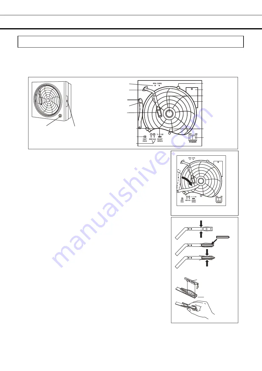
Loading the ink pen: 
1. 

Turn the power switch off for temperature recorder.


2.

 Slightly raise the end of the pen lifter and remove from the pen 

lifter stopper.    Then rotate clockwise as shown in Fig. 1. 
 

3.

 Remove the ink pen from the bag and remove its cap.    The cap 

can be conveniently kept on the pen cap holder located at the upper 
left corner. 
 

4.

 Press both sides of the pen arm as indicated by the arrows to 

open the head clamp at A and B. (See to Fig. 2 illustration 1) 

 
5.

 Position the ink pen so that the guide pins fit into the guide holes 

on the pen arm. (See to Fig. 2 illustration 2) 

 
6.

 Press the two sides of the head clamp as indicated by the arrows 

to secure the ink pen. (See to Fig. 2 illustration 3)  From the side 
view, the cartridge should fit perfectly on the arm.    Confirm that the 
pen arm is attached to both sides of the ink pen. 
 

7.

 After loading the ink pen, return the pen lifter to the original 

position.  Confirm that the pen lifter has securely entered the pen 
lifter stopper. 
 

8.

 Turn the power switch on for temperature recorder. 


Fig. 1 


Fig. 2 

Ink pen 

Ink pen 

Pen arm 

A
A


Open cover 

latch 

Key lock 

Pen arm 

Pen lifter 

Ink pen 

Chart guides 

Back-up battery 

Power switch 

Chart hub cover 
Recording


paper 

Pilot lamp 

Zero adjustment screw 

Fast feed button 

Paper speed selector   

Pen lifter stopper 

Pen cap holder 

Содержание MDF-MU300H

Страница 1: ...U300H Please read the operating instructions carefully before using this product and keep the operating instructions for future use See page 32 for all model numbers Operating Instructions Biomedical Freezer MDF MU500H ...

Страница 2: ......
Страница 3: ...RATURE SETTING P 15 SETTING OF ALARM RESUME TIME P 16 SETTING OF COMPRESSOR DELAY TIME P 17 ALARMS SAFETY FUNCTIONS P 18 ROUTINE MAINTENANCE P 19 Cleaning of cabinet P 19 Defrosting P 19 TROUBLESHOOTING P 20 DISPOSAL OF UNIT P 21 Decontamination of unit P 21 TEMPERATURE RECORDER OPTION P 26 Setting of MTR 4015LH P 26 Setting of MTR G85C P 28 BATTERY MOUNTING BOX OPTION P 30 INTERFACE BOARD OPTION ...

Страница 4: ...rating instructions are subject to change without notice for improvement of performance or function Contact our sales representative or agent if any page of the operating instructions is lost or the page order is incorrect or if the instructions are unclear or inaccurate No part of the operating instructions may be reproduced in any form without the express written permission of PHC Corporation IM...

Страница 5: ...t in a hazard to personnel possibly resulting in serious injury or death CAUTION Failure to observe CAUTION signs could result in injury to personnel and damage to the unit and associated property Symbol shows this symbol means caution this symbol means an action is prohibited this symbol means an instruction must be followed Be sure to keep the operating instructions in a place accessible to user...

Страница 6: ... Never ground the unit through a gas pipe water main telephone line or lightning rod Such grounding may cause electric shock in the case of an incomplete circuit Connect the unit to a power source as indicated on the rating label attached to the unit Use of any other voltage or frequency other than that on the rating label may cause fire or electric shock Never store volatile or flammable substanc...

Страница 7: ...ion may cause electric shock or fire When removing the plug from the power supply outlet grip the power supply plug not the cord Pulling the cord may result in electric shock or fire by short circuit Disconnect the power supply plug before moving the unit Take care not to damage the power cord A damaged cord may cause electric shock or fire Disconnect the power plug when the unit is not used for l...

Страница 8: ...or improper insertion may cause a heat or ignition Never store corrosive substances such as acid or alkali in this unit if the container cannot be sealed These may cause corrosion of inner components or electric parts Check the setting when starting up of operation after power failure or turning off of power switch The stored items may be damaged due to the change of setting Be careful not to tip ...

Страница 9: ...o 40o C Maximum relative humidity 80 for temperature up to 31o C decreasing linearly to 50 relative humidity at 40o C Mains supply voltage fluctuations up to 10 of the nominal voltage Transient overvoltages up to the levels of OVERVOLTAGE CATEGORY II Temporary OVERVOLTAGES occurring on the mains supply Applicable pollution degree of the intended environment POLUTION DEGREE 2 in most cases ...

Страница 10: ...8 FREEZER COMPONENTS 2 11 3 7 9 8 6 4 10 1 5 12 MDF MU500H MDF MU300H 4 9 7 5 11 2 1 3 9 12 10 7 8 Power cord Back Power cord Back Fixture Fixture Power switch Power switch Hole for padlock Spacer ...

Страница 11: ...ainer when defrosting since the storage container is used as a defrost water vessel 7 Storage container Made of styrol resin Be careful not to damage the storage container by a metal scraper at the time of defrosting Note Do not pull the storage container excessively The storage container may fall down 8 Access port This is used for leading a sensor or a cable of the measuring equipment to the cha...

Страница 12: ... 14 for the key lock 5 Set key SET Chamber temperature setting mode is led by pressing this key The changeable digit is flashed Pressing this key again after temperature setting memorizes the setting 6 Defrost key DEF By pressing this key for 5 seconds the refrigerating operation is stopped Pressing this key again after defrosting leads resumption of the refrigerating operation See page 19 for the...

Страница 13: ...ondition to avoid the vibration or noise Unstable condition may cause vibration or noise WARNING Install the unit on a sturdy floor If the floor is not strong enough or the installation site is not adequate this may result in injury from the unit falling or tipping over Select a level and sturdy floor for installation This precaution will prevent the unit from tipping Improper installation may res...

Страница 14: ...evel 3 Keeping the space MDF MU500H only Keep the adequate space at the back of the unit by using the spacer on the back To fix the spacer follow the procedure below Press the spacer to the condenser Pull up the lower edge to the horizontal position Push in the spacer between the condenser 4 Fixing the unit Two fixtures are attached to the rear of the frame Fix the frame to the wall with these fix...

Страница 15: ...hat the alarm lamp blinks and alarm buzzer activates Also the remote alarm is activates when the battery mounting box optional component is installed Note The alarm lamp blinks and E09 is displayed on the digital temperature indicator when the battery switch is OFF 7 Begin slowly placing items into the chamber to minimize the temperature rise The temperature alarm activates by the temperature rise...

Страница 16: ...90 seconds has passed without any key operation In this case any setting before pressing set key SET is not memorized KEY LOCK FUNCTION This unit is provided with the key lock function When the key lock is ON change of temperature setting through the key pad is not available The defrost key DEF is also ineffective The key lock is set in OFF at the factory Display Mode Function L 0 Key lock is OFF ...

Страница 17: ...y and scroll the figure to 1 When pressed the figure of settable digit changes 4 Press set key SET The first digit is flashed 5 Set the temperature to 005 with the digit shift key and numerical value shift key When pressed the changeable digit is shifted When pressed the figure of settable digit changes 6 Press set key SET Alarm temperature is memorized and the current chamber temperature is displ...

Страница 18: ...seconds The first digit is flashed 3 Set the figure to F25 with the digit shift key and numerical value shift key When pressed the changeable digit is shifted When pressed the figure of settable digit changes 4 Press set key SET The current resume time is displayed The second digit is flashed 5 Set the figure to 020 with the numerical value shift key When pressed the figure of settable digit chang...

Страница 19: ... Changing procedure for delay time change from 1 minutes to 4 minutes Description of operation Key operated Indication after operation 1 The current chamber temperature is displayed 2 Press numerical value shift key for 5 seconds The first digit is flashed 3 Set the figure to F05 with the numerical value shift key When pressed the figure of settable digit changes 4 Press set key SET The current de...

Страница 20: ...ure alarm MPR 48B1 installed In the case of power failure When the power to the unit is disconnected Alarm lamp is flashed Intermittent tone Remote alarm Battery check MPR 48B1 installed When about 3 years has passed with the power cord is connected to the outlet F1 and chamber temp are displayed alternately Battery switch check MPR 48B1 installed When battery switch is OFF at the time of alarm te...

Страница 21: ... sealed This unit requires absolutely no lubrication Clean or defrost the chamber once a month Defrosting This product is refrigerated by the direct cooling When it uses for a long time frost appears on the chamber wall side It cannot be cooled down when there is much amount of frost The defrost is mentioned in the following Use the scraper provided for removing the frost if the freezer operation ...

Страница 22: ...ple whose temperature was high in the freezer chamber An alarm is canceled naturally when it is left in these cases The cooling is poor You put too many unfrozen articles into the freezer compartment The large amount of frost is built on the chamber wall The door is opened frequently The set temperature is not inputted properly The freezer is in the direct sunlight The freezer is not installed pro...

Страница 23: ... instructions when servicing or recycling Well ventilate the room to prevent refrigerant accumulation Keep fire away when the refrigerant is contained in the product Do not damage or break the pipework Decontamination of unit Before disposal of unit with biohazardous danger decontaminate the unit to the extent possible by the user ...

Страница 24: ...thod of disposal German Benutzerinformationen zur Entsorgung von elektrischen und elektronischen Geräten private Haushalte Dieses Symbol auf Produkten und oder begleitenden Dokumenten bedeutet dass verbrauchte elektrische und elektronische Produkte nicht mit gewöhnlichem Haushaltsabfall vermischt werden sollen Bringen Sie zur ordnungsgemäßen Behandlung Rückgewinnung und Recycling diese Produkte zu...

Страница 25: ...illez contacter les autorités locales ou votre revendeur afin de connaître la procédure d élimination à suivre Spanish Información sobre la eliminación para los usuarios de equipos eléctricos y electrónicos usados particulares La aparición de este símbolo en un producto y o en la documentación adjunta indica que los productos eléctricos y electrónicos usados no deben mezclarse con la basura domést...

Страница 26: ...r e peça informações sobre o método de eliminação correcto Italian Informazioni per gli utenti sullo smaltimento di apparecchiature elettriche ed elettroniche obsolete per i nuclei familiari privati Questo simbolo sui prodotti e o sulla documentazione di accompagnamento significa che i prodotti elettrici ed elettronici usati non devono essere mescolati con i rifiuti domestici generici Per un corre...

Страница 27: ...op met de lokale overheid of uw leverancier en vraag wat de juiste verwijderingsmethode is Swedish Information om kassering för användare av elektrisk elektronisk utrustning privata konsumenter Om denna symbol finns på produkterna och eller medföljande dokumentation betyder det att förbrukade elektriska och elektroniska produkter inte ska blandas med vanliga hushållssopor För korrekt hantering inh...

Страница 28: ...ecording paper 1 The information on the temperature recording paper is shown in Fig 1 2 Pull the cartridge up after opening the cover See Fig 2 The cover can be opened by turning the knob counterclockwise 3 Put the recording paper into the cartridge with the printed surface out from the leading end as shown in Fig 3 4 Pass the recording paper under the arm through between the guide plate See Fig 4...

Страница 29: ...paper storage send all the recording paper in the recording paper storage first turning the gear Battery replacement To replace the battery turn the knob counterclockwise to open the cover Place the battery in the dry cell case according to the plus minus indications on the bottom of the dry cell case See Fig 6 Replace the battery once a year Note This temperature recorder is designed for the mang...

Страница 30: ...e head clamp at A and B See to Fig 2 illustration 1 5 Position the ink pen so that the guide pins fit into the guide holes on the pen arm See to Fig 2 illustration 2 6 Press the two sides of the head clamp as indicated by the arrows to secure the ink pen See to Fig 2 illustration 3 From the side view the cartridge should fit perfectly on the arm Confirm that the pen arm is attached to both sides o...

Страница 31: ...When the recording paper speed is set to 32 days The center of the recording paper is divided into 32 equal sections The lines extending from these lines serve as the 32 day time scale Fig 4 Stopping recording 1 Turn OFF the power switch 2 When recording is stopped for a prescribed period place the caps back on the ink pen to prevent the ink from evaporating Replacement the recording paper 1 Sligh...

Страница 32: ...r power failure alarm and remote alarm terminal are included in the battery mounting box Contact our sales representative or agent for the installation of the battery mounting box INTERFACE BOARD OPTION The running log of the freezer can be sent to a personal computer by using an interface board MTR 480 Important For the installation of an interface board the battery mounting box is needed since t...

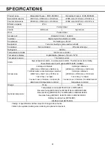
Страница 33: ...e alarm Low temperature alarm Thermal sensor abnormality Power failure alarm with optional MPR 48B1 installed Accessories 4 storage containers W446 mm x D369 mm x H220 mm 1 defrost water vessel storage container W487 mm x D221 mm x H155 mm 1 set of key 1 scraper 1 sensor cover 2 binders 4 screws for attachment of temperature recorder 4 storage containers W290 mm x D536 mm x H238 mm 6 storage conta...

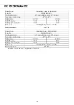
Страница 34: ...on 80 W 80 W Noise level 40 dB A background noise 20 dB Maximum pressure 1060 kPa Product name Biomedical Freezer MDF MU500H Model No MDF MU500H PE Cooling performance 30o C ambient temperature 30o C no load Temperature control range 20o C to 30o C Rated voltage AC 230 V AC 240 V Rated frequency 50 Hz 50 Hz Rated power consumption 85 W 85 W Noise level 40 dB A background noise 20 dB Maximum pressu...

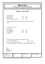
Страница 35: ...f the unit Unit interior No contamination Decontaminated Contaminated Others 3 Instructions for safe repair maintenance disposal of the unit a The unit is safe to work on b There is some danger see below Procedure to be adhered to in order to reduce safety risk indicated in b below Date Signature Address Division Telephone Product name Model Serial number Date of installation Biomedical Freezer MD...

Страница 36: ...Printed in Japan LDCL034000 0 S0418 0 PHC Corporation 2018 1 1 1 Sakada Oizumi machi Ora gun Gunma 370 0596 Japan ...

Отзывы: