


8
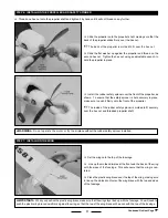
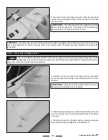
STeP 4: CONNeCTING THe PuSHROD WIReS
PRO TIP
❑
Carefully snap the plastic clevis on the pushrod wire into the
outermost hole
in the elevator control horn.
We suggest installing the clevis into the outermost
hole in the control horn for your first few flights. This will make it
easier to control the airplane. Once you're proficient at flying the
airplane, you can move the pushrod wire into the middle or inner
hole to increase the control response.
✦
IMPORTANT
✦
When you snap the plastic clevises into the plastic control horns in the next two procedures, the elevator and
rudder (control surfaces on the back of the horizontal tail and the vertical tail) might not be centered. That's okay for now. We'll
center them by adjusting the clevises when we test the radio system later.
PRO TIP
❑
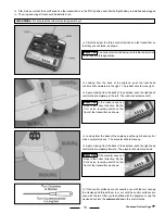
Carefully snap the plastic clevis on the pushrod wire into the
outermost hole
in the rudder control horn.
We suggest installing the clevis into the outermost
hole in the control horn for your first few flights. This will make it
easier to control the airplane. Once you're proficient at flying the
airplane, you can move the pushrod wire into the middle or inner
hole to increase the control response.
Continued On Next Page
☛
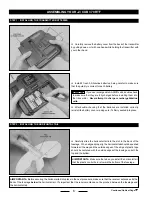
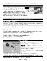
STeP 5: INSTALLING THe LANDING GeAR ASSeMBLY
❑
Install the landing gear assembly by first gently squeezing the
two landing gear wire legs together, then by pushing the landing gear
assembly firmly into the slot in the bottom of the fuselage until the
assembly "snaps" into place.
☞
The straight edge of the plastic landing gear fairings should be
toward the front of the airplane, as shown.
✦
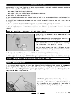
IMPORTANT
✦
After installation, pull down on the landing gear assembly to ensure that it's snapped firmly into place.


