


E.Installing Cylinder and piston
a.Installing piston and piston rings
1.Lubricate the piston rings by motor oil.
NOTICE:
a.Be careful not to scratch the piston
and not to break the piston ring.
b.The mark (on the ring) should be
upward when installing.
c.after installing, the ring should be
smoothly rotated.
2.Clean up the residual gasket on the
crankcase.
3.Assembly the piston, piston pin and piston pin
clip.
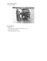
b.Installing piston
1.Fix the lock pin and gasket on the crankcase.
2.Lubricate the Cylinder inner surface, piston and piston rings by Motor Oil.
3.Install the piston ring into the cylinder carefully.
NOTICE:
Do not drop other objects into the crankcase.
NOTICE:
a.The mark “IN” on the piston tip should face
to the INLET side.
b.Do not drop the piston pin clip into the
crankcase and to clog the crankcase with rags.
NOTICE:
a.The piston ring cannot be damaged or cracked.
b.The cutting section of three rings must be arranged at intervals of 120
°
Содержание ALLORO 125
Страница 1: ...Manufactured by Motive Power Industry Co Ltd ...
Страница 17: ...C Chassis appearance 1 Apply oil 1 2 2 Apply grease 3 4 5 6 7 8 1 2 3 4 5 6 7 8 ...
Страница 18: ...D Wheel bearing Final transmission mechanism gear oil Speedometer gear clean grease ...
Страница 60: ...C Driving pulley 1 Take off the 10 screws of left Cover remove the left cover 2 Take off the left cover ...
Страница 62: ...7 Remove the start idle gear fixing plate 8 Take off the idle gear ...
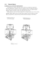
Страница 82: ... 7 Crankcase Crankshaft A Disassembling diagram ...
Страница 94: ... 1 Lubrication System ...
Страница 118: ... 7 A C Generator A Dismantling AC generator B Installing AC generator ...
Страница 132: ......
Страница 164: ... 3 Recharge system A Recharge system diagram for M2 50 ...
Страница 165: ...B Recharge system diagram for M2 125 150 ...
Страница 170: ...46 Wiring diagram for M2 50 ...
Страница 171: ...47 Wiring diagram for M2 125 150 ...
Страница 172: ...48 Wiring diagram for M2 150 4V ...
Страница 173: ...49 Wiring diagram for M2 200 ...
Страница 174: ......
Страница 175: ......
Страница 176: ...50 Wiring diagram for M2 250 ...
Страница 188: ...PGO 200 220 engine dismantle crankshaft from the left crankcase don t damage the oil impact the crankshaft ...
Страница 192: ...1 6 3 Electric system Carburetor model electric General maintenance Engine Management System ...
Страница 198: ...7 Fuse wire white white Main fuse layout relay fuse layout reserved fuse layout Red white Red Red white Red black ...
Страница 201: ...10 G MAX 200 220 Specified engine oil synthetic 1000ml ...
Страница 202: ...11 Engine oil gear oil Drain of engine oil drain of gear oil Gear oil filling Replace 110cc total 130cc ...
Страница 206: ...15 CVT sponge Clean with compressed air or replace a new one 1 loosen 3 bolts 2 take off the sponge ...
Страница 209: ...18 Spark plug Dismantle the right lower cover Loosen with the special tool Spark plug C7E carburetor or CR7E EMS model ...
Страница 210: ...19 Ignition coil Dismantle the right lower cover You can see the ignition coil clearly ...
Страница 215: ...1 6 5 Engine Management System EMS ...
Страница 216: ...2 EMS index PGO 2nd stage EMS structure EMS units EMS diagnostic ...
Страница 217: ...3 Feature of PGO 2nd stage EMS feature 1 small light 2 integrity 3 accuracy 4 simple ...
Страница 220: ...6 EMS units ...
Страница 221: ...7 噴油嘴 Throttle position sensor Intake pressure sensor injector Idle Speed Controller ...
Страница 222: ...8 crank speed sensor Fuel pump Assy Transistor ignition coil comp Oxygen sensor Engine temperature sensor ...
Страница 223: ...9 ECU Electronic Control Unit Topple snsor Second air solenoid ...
Страница 224: ...10 Important PIN no of ECU ECU PIN 1 PIN 18 PIN 19 PIN 36 PIN ...
Страница 228: ...14 Measure engine temperature sensor T resistance KΩ 20 18 800 KΩ 40 1 136 KΩ 100 0 155 KΩ usually 1 5 5 5 KΩ ...
Страница 230: ...16 Throttle position sensor TPS Lb output Pu power 5V Gr ground Lb Gr throttle output V close 0 6 0 02V WOT 3 8 0 10V ...
Страница 235: ...21 Oxygen sensor W heater 12V 2 couple 8Ω Gr ground B output ...
Страница 236: ...22 injector function inject the gas mixed with air theory control the opening time interval to decide the gas amount ...
Страница 237: ...23 injector time msec Gas amou nt feeding injecting R B output 12V Br W output 12V each terminal virus ground is 12V ...
Страница 240: ...26 Fuel pump R B output 12V B ground R B B voltage 12V resistance 1KΩ ...
Страница 243: ...29 ISC Idle Speed Control W ISC A R B ISC B G ISC B Gr ISC A ISC unit R A A 80Ω B B 80Ω ...
Страница 245: ...31 ISC Step motor ISC By pass air Throttle body engine Throttle valve Air flow ISC Idle Speed Control ...
Страница 248: ...34 EMS fuses 7 5A 10A 5A 1A 10A 15A ...
Страница 250: ...36 6 6 EMS diagnostic ...
Страница 251: ...37 part no S320840G01 name quick diagnostic Quick diagnostic ...
Страница 254: ...40 part number S320891G01 name software adapter PC diagnostic software adapter ...
Страница 255: ...41 part number S320838G01 name connect cable PC diagnostic ...
Страница 258: ...44 6 7 EMS system Repairing tool ...
Страница 259: ...45 pocket tester wiring pocket tester wiring part no S905310005 ...
Страница 260: ...46 Ignition gauge connect minimum distance 6mm Plug cap ground ...
Страница 261: ...47 Fuel pressure gauge fuel pressure gauge part no S905330008 ...
Страница 263: ...49 6 8 General Electric units ...
Страница 264: ...50 G MAX 220 made in electric diode Storage light controler fuse relay Fuel pump Assy fuel jet relay ...
Страница 265: ...51 Signal flasher relay LED within the leg shield cover dismantle the leg shield cover first ...
Страница 266: ...52 regulator within the right body cover dismantle 1 luggage comp 2 rear rack 3 body cover ...
Страница 267: ...53 Fuel gauge below the middle cover dismantle 1 middle cover ...
Страница 268: ...54 Measure the fuel gauge gray output black ground gray black F 4 10Ω E 80 90Ω ...
Страница 269: ...55 Starting relay within the right body cover dismantle 1 luggage comp 2 middle cover 3 rear rack 4 body cover ...
Страница 271: ...56 EMS relays within the right body cover dismantle 1 luggage comp 2 middle cover 3 rear rack 4 body cover ...
Страница 272: ...57 EMS relays wiring A EMS system Dg O Gr B Bl W B fuel pump injector R W R W R B Db C headlamp O O Y W Y A B C ...
Страница 275: ......


