background image


PFT Conveying Pump ZP 3 XL MIX Part 2 Overview – Operation - Spare Parts Lists 

Spare Parts Drawing, Spare Parts List 


44  

Fehler! Formatvorlage nicht definiert.


15.2 Vibrator Sieve with External Vibrator 


Содержание ZP 3 XL MIX

Страница 1: ...g Manual PFT Conveying Pump ZP 3 XL MIX Part 2 Overview Operation Spare Parts Lists Article number of Operating Manual 00 17 51 91 Article number of machine Spare Parts List 00 14 80 20 Read the Opera...

Страница 2: ...nicht definiert Knauf PFT GmbH Co KG Postfach 60 97343 Iphofen Einersheimer Strasse 53 97346 Iphofen Germany Telephone 49 9323 31 760 Telefax 49 9323 31 770 Technical Hotline 49 9323 31 1818 info pft...

Страница 3: ...Transportation 16 5 2 Transportation Inspection 17 5 3 Transportation 17 5 4 Packaging 18 6 Safety 19 6 1 Safety Fundamentals 19 7 Preparation 20 7 1 Erecting the Machine 20 7 2 Switch Cabinet Prepar...

Страница 4: ...he Swivel Bearing and Gear Rim 37 13 5 Environmental Protection 37 13 6 Retighten the Pump Unit 38 13 7 Detaching the Pump 38 13 8 Measures Taken after Maintenance 39 13 9 Decommissioning in Emergency...

Страница 5: ...king It is constituent part of the product and must always be kept near the equipment so that it is always at the disposal of the personnel When handing over the equipment to a third party also hand o...

Страница 6: ...width 1050 mm Overall height 1500 mm Tank volume PFT ZP 3 XL 130 Litres Filling volume of mixing drum 145 Litres 1 5 Power Rating Electrical Item Value Unit Voltage three phase current 50 400 V Curren...

Страница 7: ...lue Unit Maximum operation period once 8 hours 1 7 Power Rating Pumping capacity 2 L 6 Item Value Unit Pumping capacity approx 30 l min Operating pressure max 20 bar Guideline value depending upon pum...

Страница 8: ...Formatvorlage nicht definiert 1 10 Dimension Sheet Fig 2 Dimension Sheet 1 11 Type Plate Fig 3 Type plate The type plate is located on the material container on the motor side and includes the followi...

Страница 9: ...9 2 Overview Fig 4 Overview of the subassemblies 1 Hand wheel 2 Mixing drum 3 Motor housing 4 Vibrating sieve 5 Switch cabinet 6 Wheel with steel rim 7 Pump stock tank 8 Cleaning nozzle 9 Telescopic t...

Страница 10: ...00098601 Fig 5 Subassembly switch cabinet Switch cabinet 1 Control voltage ON OFF 2 Main reversing switch is also Emergency OFF switch 3 Connection for mains power 4 Multiple contact switch for vibra...

Страница 11: ...r switch On 4 Mixer switch Off 5 Hand wheel 6 Mixing drum 7 Telescopic tube support 3 3 Subassembly Description Frame and Vibrating Sieve Fig 7 Subassembly drum mixer Frame and vibrating sieve 1 Cover...

Страница 12: ...Description 7 5kW 175 1 min Fig 9 Subassembly of geared motor Geared motor 7 5kW 175 1 min Article number 20143501 3 6 Subassembly Description of Air Compressor LK 250 Fig 9 Air compressor Fig 9 1 Pr...

Страница 13: ...pump conveys the plaster or mortar directly to the place of processing after admixing inside the attached drum mixer The delivery capacity can be adjusted to the material requirement The PFT ZP 3 XL M...

Страница 14: ...activated Fig 13 Multiple contact switch Automatic Position Automatic Vibrator runs on automatic pulse pause 3 10 Remote Control Operation Fig 14 Remote control Working with Spray Device If the contr...

Страница 15: ...PFT Conveying Pump ZP 3 XL MIX Part 2 Overview Operation Spare Parts Lists ZP 3 Variants Overview Fehler Formatvorlage nicht definiert 15 4 ZP 3 Variants Overview...

Страница 16: ...ckaging material Use only the provided hoisting points Remove packaging just shortly prior to assembly Floating Loads WARNING Life Hazard Through Floating Loads When lifting loads life hazard may be p...

Страница 17: ...ansportation by means of a crane hoist the pump with a rope at the hoisting eyelets 1 Note the following conditions Crane and hoisting means must be dimensioned for the weight of the packaged pieces T...

Страница 18: ...you should not destroy the packaging but remove it shortly prior to assembly Handling Packaging Materials If no return agreement has been made for the packaging material sort the materials based on t...

Страница 19: ...of Injury due to Improper Operation Improper operation can lead to serious personal injury or property damages Therefore Do all operational steps in accordance with the information in this Operating M...

Страница 20: ...elescopic tube support to stand in a stable manner on a level surface and secure it against unintentional movement If necessary use pads when the support foot 1 is used so that the machine does not si...

Страница 21: ...tch 3 7 3 Connecting the Drum Mixer Fig 22 Connecting the drum mixer Connect the extension cable 5x16A 1 5 meters long from the switch cabinet to the drum mixer 1 7 4 Mortar Pressure Manometer Fig 23...

Страница 22: ...d injure the bystanders Fig 25 Ready for operation Turn the main reversing switch on I Machine is operative 8 Putting the Drum Mixer into Operation 8 1 Mixing Position for Drum Mixer Fig 26 Locking di...

Страница 23: ...nsists of bonding agents e g lime cement anhydrite water and extra charge materials sand types Always use only the best additive materials for example washed sand Consult with a specialist on this Add...

Страница 24: ...n the drum mixer Switch On the mixer As for the mixer with a three phase current motor the rotating direction of a drum mixer must be checked after turning On It must rotate in anticlockwise direction...

Страница 25: ...ng until mortar is discharged at the mortar hose end HINT Never let the pump run dry since the service life of the pump will be shortened 9 2 Connecting the Spray Device Fig 33 Connect the spray devic...

Страница 26: ...ceeded thicker mortar hoses must be used Fig 33 Open the air cock 6 Hold the spray device towards the wall to be plastered 7 Guarantee that no persons are in the exit area of mortar 8 Open air cock 1...

Страница 27: ...stance between air nozzle pipe and nozzle opening corresponds to the diameter of the nozzle 9 7 Applying the Wall Mortar Fig 35 Remote control HINT When working without air e g when pumping wall morta...

Страница 28: ...the operation site 4 If necessary alarm a medical practitioner and firemen 5 Rescue persons from the danger zone initiate first aid measures 6 Keep access roads free for rescue vehicles After the Res...

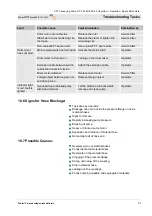
Страница 29: ...ration site about the fault 5 Depending upon the kind of fault let it to be eliminated by authorised professional personnel or eliminate it yourself HINT The following troubleshooting table gives info...

Страница 30: ...vice fitter Motor protection switches released In the switch cabinet turn the motor protection switch to Position 1 Service fitter Operation button On not pressed Press Operation button On Operator Pr...

Страница 31: ...r defective Replace mixer motor Service fitter Drum mixer does not start Foreign object between gear rim and drive pinion Remove foreign object Operator Indicator light is red fault is lighted Overloa...

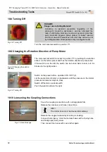
Страница 32: ...al switch is locked in position 0 by pushing the selection slide 1 to the left as preset and thus the rotation direction is preselected If the switch is on the left the switch can be turned back to ze...

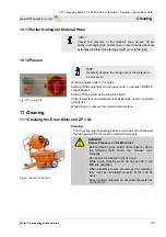
Страница 33: ...he system using the main switch Clean the system and material hoses depending on the curing time of material While doing so observe the ambient temperature 11 Cleaning 11 1 Cleaning the Drum Mixer and...

Страница 34: ...th hard objects such as hammer shovel etc Fig 44 Opening the cleaning cover At the end of work empty ZP 3 XL Clean the protective grating and material container from rest material with water jet and p...

Страница 35: ...the sponge ball exits at the hose end Repeat this process at least twice Hint For different hose diameters the corresponding sponge balls should be used Sponge ball for 35 hoses Article Number 202106...

Страница 36: ...connection cable DANGER Life Hazard by Electric Current Contact with components under voltage poses life hazard Activated electrical components can execute uncontrolled motions and lead to severe inju...

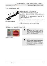
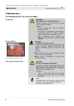
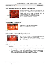
Страница 37: ...al container Monthly grease 2 the transmission seal 13 4 Lubricating the Swivel Bearing and Gear Rim Fig 52 Greasing the swivel bearing Drum mixer and drive shaft of the mixer have ball bearings with...

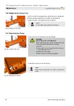
Страница 38: ...mp uniformly HINT Do not tighten pump during the operation 13 7 Detaching the Pump Fig 54 Loosen collar nuts Loosen the nuts on both sides of the pump flange DANGER Excess Pressure on the Machine When...

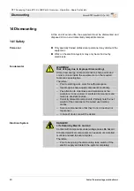
Страница 39: ...ger situations machine motions must be stopped very quickly and power supply cut out Decommissioning in Emergency In danger cases proceed as follows 1 Turn off the main switch immediately 2 Secure the...

Страница 40: ...ed tools can cause injuries Therefore Prior to starting work cater for sufficient space Handle open sharp edged components cautiously Pay attention to orderliness and cleanliness at the workplace Loos...

Страница 41: ...the rest processing materials and dispose of them in an environmentally compatible manner 14 3 Waste Disposal Provided no return nor disposal agreement has been made deliver dismantled components to t...

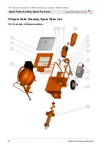
Страница 42: ...ng Pump ZP 3 XL MIX Part 2 Overview Operation Spare Parts Lists Spare Parts Drawing Spare Parts List 42 Fehler Formatvorlage nicht definiert 15 Spare Parts Drawing Spare Parts List 15 1 Overview of Su...

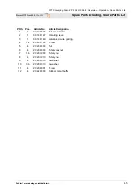
Страница 43: ...0 19 98 Housing motor seal 5 1 00 10 21 27 Protective grating 6 1 00 10 24 92 Plastic hood 7 1 00 10 36 19 Material container with frame 8 2 00 14 66 94 Wheel 9 1 00 14 70 77 Fixture compressor 10 1 0...

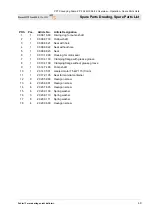
Страница 44: ...PFT Conveying Pump ZP 3 XL MIX Part 2 Overview Operation Spare Parts Lists Spare Parts Drawing Spare Parts List 44 Fehler Formatvorlage nicht definiert 15 2 Vibrator Sieve with External Vibrator...

Страница 45: ...o Article Designation 1 1 00 12 86 06 External vibrator 2 1 00 14 81 47 Vibrating sieve 3 1 00 14 81 49 Galvanized wire grating 4 14 20 20 61 00 Screw 5 4 20 20 64 00 Nut 6 4 20 20 66 03 Safety cap nu...

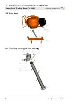
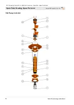
Страница 46: ...onveying Pump ZP 3 XL MIX Part 2 Overview Operation Spare Parts Lists Spare Parts Drawing Spare Parts List 46 Fehler Formatvorlage nicht definiert 15 3 Drum Mixer 15 4 Telescopic tube support D48 600...

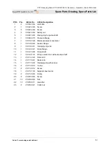
Страница 47: ...5 Telescopic tube support complete 4 2 20 20 72 00 Safety nut 5 2 20 20 77 10 Screw 6 2 20 20 93 13 U washer Telescopic Tube Support POS Pcs Article No Article Designation 1 1 00 14 84 39 Telescopic t...

Страница 48: ...PFT Conveying Pump ZP 3 XL MIX Part 2 Overview Operation Spare Parts Lists Spare Parts Drawing Spare Parts List 48 Fehler Formatvorlage nicht definiert 15 5 Gear Motor with Pump Unit...

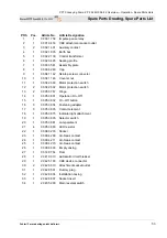
Страница 49: ...without hole 5 1 00 09 88 23 Seal 6 1 00 10 19 98 Housing for motor seal 7 1 00 10 41 30 Clamping flange with grease groove 8 1 00 10 41 38 Clamping flange without grease groove 9 1 00 14 74 98 Pump...

Страница 50: ...PFT Conveying Pump ZP 3 XL MIX Part 2 Overview Operation Spare Parts Lists Spare Parts Drawing Spare Parts List 50 Fehler Formatvorlage nicht definiert 15 6 Pump Unit 2 L6...

Страница 51: ...75 Pressure flange 7 1 00 10 22 29 Mortar pressure manometer 8 1 00 12 89 46 Suction flange 9 1 00 13 92 41 Clamping clip 2 L6 10 1 00 14 69 21 Pump flange 11 1 00 14 74 98 Pump shaft 12 1 00 14 91 74...

Страница 52: ...PFT Conveying Pump ZP 3 XL MIX Part 2 Overview Operation Spare Parts Lists Spare Parts Drawing Spare Parts List 52 Fehler Formatvorlage nicht definiert 15 7 Switch Cabinet Article Number 00 09 86 01...

Страница 53: ...0 04 26 02 Motor protection switch 13 2 00 05 37 67 Hinge 14 1 00 05 38 31 Operation On Off 15 1 00 05 38 32 On Off button 16 3 00 05 38 34 Fastening adapter 17 3 00 05 38 35 Contact element 18 1 00 0...

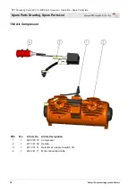
Страница 54: ...Spare Parts Drawing Spare Parts List 54 Fehler Formatvorlage nicht definiert 15 8 Air Compressor POS Pcs Article No Article Designation 1 1 00 00 79 15 Compressor 2 1 20 13 41 00 Handle 3 1 20 13 51...

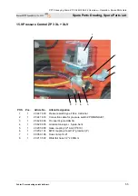
Страница 55: ...ticle Designation 1 1 20 44 76 00 Pressure switch type FF4 4 0 22 4bar 2 1 20 44 76 33 Connection cable for pressure switch ZP3 MONOJET 3 1 20 42 86 06 Pin insert 4 pole HAN 3A 4 1 20 42 86 05 Grommet...

Страница 56: ...PFT Conveying Pump ZP 3 XL MIX Part 2 Overview Operation Spare Parts Lists Circuit Diagram 56 Fehler Formatvorlage nicht definiert 16 Circuit Diagram...

Страница 57: ...PFT Conveying Pump ZP 3 XL MIX Part 2 Overview Operation Spare Parts Lists Circuit Diagram Fehler Formatvorlage nicht definiert 57...

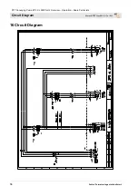
Страница 58: ...PFT Conveying Pump ZP 3 XL MIX Part 2 Overview Operation Spare Parts Lists Circuit Diagram 58 Fehler Formatvorlage nicht definiert...

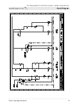
Страница 59: ...PFT Conveying Pump ZP 3 XL MIX Part 2 Overview Operation Spare Parts Lists Circuit Diagram Fehler Formatvorlage nicht definiert 59...

Страница 60: ...iagram 60 Fehler Formatvorlage nicht definiert WE CATER FOR THE FLOW OF THINGS Knauf PFT GmbH Co KG Postfach 60 97343 Iphofen Einersheimer Strasse 53 97346 Iphofen Germany Telephone 49 9323 31 760 Tel...

Отзывы: