PFT SILOMAT E 140 VAE Скачать руководство пользователя страница 9

FT Silomat E 140 

(VAE)

 Operating Instructions        

                                                           05.2008 

Knauf PFT GmbH & Co. KG  

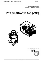
 Overview of Silomat E 140 item number 00 08 90 56 


1 Control 

box


Pneumatic pressure gauge


3 Carryable 

frame


Connection of air to conveying container


5 Pressure 

control


6 Safety 

switch


7 Filter


8 Carrying 

handle


9  Hopper lubricating nipples


10  Compressor


11 Counter flow valve


12  Connection of air from compressor


13  Tap for bypass


14 Tap 

bypass


15  Emulgator cleaning cover


16  Connection of material hose to cleaning machine


17 Conveying container


18 Flap


19  Connection of control cable from control box


20  Motor and drive


21  Motor and drive hand wheel for closing the flap 

when there’s a power failure


22 Intermediate 

piece


23  Silo outlet flap (not in scope of delivery)


24  Silo/Container (not in scope of delivery)


25  Vibrator (not in scope of delivery)


Содержание SILOMAT E 140 VAE

Страница 1: ...uctions 05 2008 Knauf PFT GmbH Co KG 1 OPERATING INSTRUCTIONS Item number of the operating instructions 00 08 91 21 Item number of the parts list machine 00 08 90 56 PNEUMATIC CONVEYING SYSTEM PFT SIL...

Страница 2: ...eying container item number 00 08 90 77 22 Replacement part list rollable conveying container item number 00 08 90 77 23 Drawing rollable conveying container item number 00 08 90 77 24 Replacement par...

Страница 3: ...r It is prohibited to forward this document even excerpts without our written authorisation All technical specifications diagrams etc are subject to copyright law All rights errors and modifications a...

Страница 4: ...rame with compressor and control box 200 210 kg Permanent noise pressure level 85 1 dB depending on material quality and weight conveying height and hose diameter Setting values Relay Function Descrip...

Страница 5: ...to ensure that it cannot be switched back on accidentally for example lock the main switch and remove the key or attach a warning sign to the main switch 10 Before cleaning the machine with a water j...

Страница 6: ...will be able to use our machine in a safe and quality assuring manner for a long time to come WARNING If additional parts that are not specified in these operating instructions are installed for speci...

Страница 7: ...formation regulations and restrictions for the prevention of damage The machine should only be used as intended in a perfect technical condition and in compliance with safety regulations and the opera...

Страница 8: ...n the filling time has elapsed the flap closes again Closed position The conveying container is now sealed pressure tight to the silo container Now the compressor begins to work and blows air through...

Страница 9: ...ples 10 Compressor 11 Counter flow valve 12 Connection of air from compressor 13 Tap for bypass 14 Tap bypass 15 Emulgator cleaning cover 16 Connection of material hose to cleaning machine 17 Conveyin...

Страница 10: ...r connection 3 Request connection rotary wing sensor mixer pump 4 Program button manual automatic 5 Pressure switch off 6 Pressure switch on 7 Fault 8 Control lamp change direction of rotation 9 Main...

Страница 11: ...r hose from the compressor at the conveying container Switch on the compressor in doing so observe the direction of rotation Air must escape at the fast coupling remove rubber hose If the direction of...

Страница 12: ...d not only be laid out flatly We therefore recommend that you create raises e g at the hose coupling by means of for example two pallets placed upright Connect the air hose from the conveying containe...

Страница 13: ...automatic switch 5 to the automatic position and press the green operating switch ON 6 As soon as the level sensor reports EMPTY The locking flap opens and during the set filling time the conveying c...

Страница 14: ...ore the tap of the upwards leading air line must be opened Measures to be taken when work is finished or interrupted Switch off the system by pressing the red pressure switch 7 OFF Turn the hand autom...

Страница 15: ...cannot be hit by discharged material No other persons should be in the vicinity Clearing hose blockages Depressurize and de energize the conveying system see above Disconnect conveying hoses in the vi...

Страница 16: ...d wheel 9 Close the silo outlet flap 11 Turn the hand 0 automatic switch 5 to the HAND position Turn the main reversing switch 8 to the I position Press the operating switch 6 ON Blow the conveying co...

Страница 17: ...til it is empty Turn the main reversing switch 8 to the position 0 Remove the emulgator cleaning cover by opening both eye screws 13 M20x100 key width 30 Separate the emulgator filters 14 by removing...

Страница 18: ...running Before beginning the maintenance work de energize the compressor Clean the intake filter 17 weekly If the filter is too dirty the air output is reduced and the compressor overheats Blow out t...

Страница 19: ...rs 20 of 32 mm may not be gone below When replacing the sliders blow the housing out with dry air When dismantling top up the grease in the rolling bearings to replace the amount used Transportation a...

Страница 20: ...contaminated or stuck Switch to automatic Replace conveying relay K8 See page 16 Cleaning emulgator filters Replace end switch Tap contents out of filters replace if required Program isn t running Fi...

Страница 21: ...control box PFT bag filling hopper item number 20 70 61 00 The bag filling hopper is screwed on to the conveying container It is for filling the system with bagged material PFT bypass for conveying ai...

Страница 22: ...FT Silomat E 140 VAE Operating Instructions 05 2008 Knauf PFT GmbH Co KG 22 Replacement part drawing conveying container item number 00 08 90 77...

Страница 23: ...hose 1 x 230 mm 9 2 20 21 51 55 Tap 1 internal thread DIN 2990 PN 35 with stop for air tap 10 1 20 65 66 00 Coupling C DIN 1 internal thread 11 1 20 20 41 50 T piece 1 external thread no 135 zinc pla...

Страница 24: ...FT Silomat E 140 VAE Operating Instructions 05 2008 Knauf PFT GmbH Co KG 24 Drawing rollable conveying container item number 00 08 90 77...

Страница 25: ...ontrol disc 33 2 20 45 65 10 Micro switch for motor and drive new 34 1 20 56 18 00 Hand wheel motor and drive 35 4 20 20 99 31 Hex screw M10 x 25 DIN 933 zinc plated 36 1 00 08 90 78 Locking flap TYPE...

Страница 26: ...FT Silomat E 140 VAE Operating Instructions 05 2008 Knauf PFT GmbH Co KG 26 Drawing control box exterior item number 20 44 30 12...

Страница 27: ...IP 67 M22 T D 13 1 00 05 38 76 Button stop for air tap with zero position and 2x latching type S1 14 1 00 05 38 38 Button stop for air tap 3 positions with 2 closers complete M22 15 1 20 45 52 00 Main...

Страница 28: ...FT Silomat E 140 VAE Operating Instructions 05 2008 Knauf PFT GmbH Co KG 28 Drawing control box interior item number 00 09 07 62...

Страница 29: ...31 24 Door SILOMAT C 11 1 00 03 62 49 Lock control box two way key bit 12 1 20 44 45 00 Key for control box 13 1 20 44 72 00 Automatic plumb level DIL ER22 42 V K1 14 2 00 08 52 93 Auxiliary contact D...

Страница 30: ...FT Silomat E 140 VAE Operating Instructions 05 2008 Knauf PFT GmbH Co KG 30 Drawing carryable frame item number 00 09 86 40...

Страница 31: ...x 20 DIN 933 zinc plated 4 2 20 20 72 00 Nut M8 DIN 985 zinc plated 5 4 20 20 72 00 Nut M8 DIN 985 zinc plated 6 4 20 20 78 00 Hex screw M8 x 30 DIN 933 zinc plated 7 4 20 56 66 15 Folding carrying ha...

Страница 32: ...FT Silomat E 140 VAE Operating Instructions 05 2008 Knauf PFT GmbH Co KG 32 Drawing compressor item number 00 10 88 96...

Страница 33: ...00 09 06 32 Housing intake filter KDT 3 140 dry running compressor 5 1 00 09 06 34 Intake filter KDT 3 140 dry running compressor 6 1 00 10 47 85 Intake tube KDT for il free compressor 7 1 Available o...

Страница 34: ...FT Silomat E 140 VAE Operating Instructions 05 2008 Knauf PFT GmbH Co KG 34 Drawing pressure control Silomat E 140 item number 00 08 90 68...

Страница 35: ...1 4 1 1 4 1 2 internal thread no 130 5 3 20 20 32 70 Double nipple 1 1 4 x 80 no 23 zinc plated 6 1 00 08 90 13 Counter flow valve 1 1 4 internal thread PN16 red brass 7 1 20 56 49 00 Safety valve R 1...

Страница 36: ...FT Silomat E 140 VAE Operating Instructions 05 2008 Knauf PFT GmbH Co KG 36 Drawing rubber pressure hose item number 20 65 09 00...

Страница 37: ...09 00 Rubber pressure hose NW 32 approx 7 5 m with couplings C 2 1 20 65 82 00 Gasket coupling C DIN 3 1 20 65 52 00 Suction coupling C 32 for 20 65 09 00 4 1 00 08 90 79 Reduction coupling C Geka 5 1...

Страница 38: ...FT Silomat E 140 VAE Operating Instructions 05 2008 Knauf PFT GmbH Co KG 38 Circuit diagram main power S163627B...

Страница 39: ...FT Silomat E 140 VAE Operating Instructions 05 2008 Knauf PFT GmbH Co KG 39 Circuit diagram control current S163628B...

Страница 40: ...2008 Knauf PFT GmbH Co KG 40 WE KEEP THINGS MOVING Knauf PFT GmbH Co KG Postfach 60 97343 Iphofen Germany Einersheimer Stra e 53 97346 Iphofen Germany Telephone 49 0 93 23 31 1818 Fax 49 0 93 23 31 77...

Отзывы: