background image


Inhaltsverzeichnis 


2017-08-07 


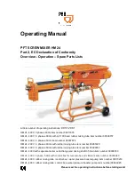
Operating Manual 

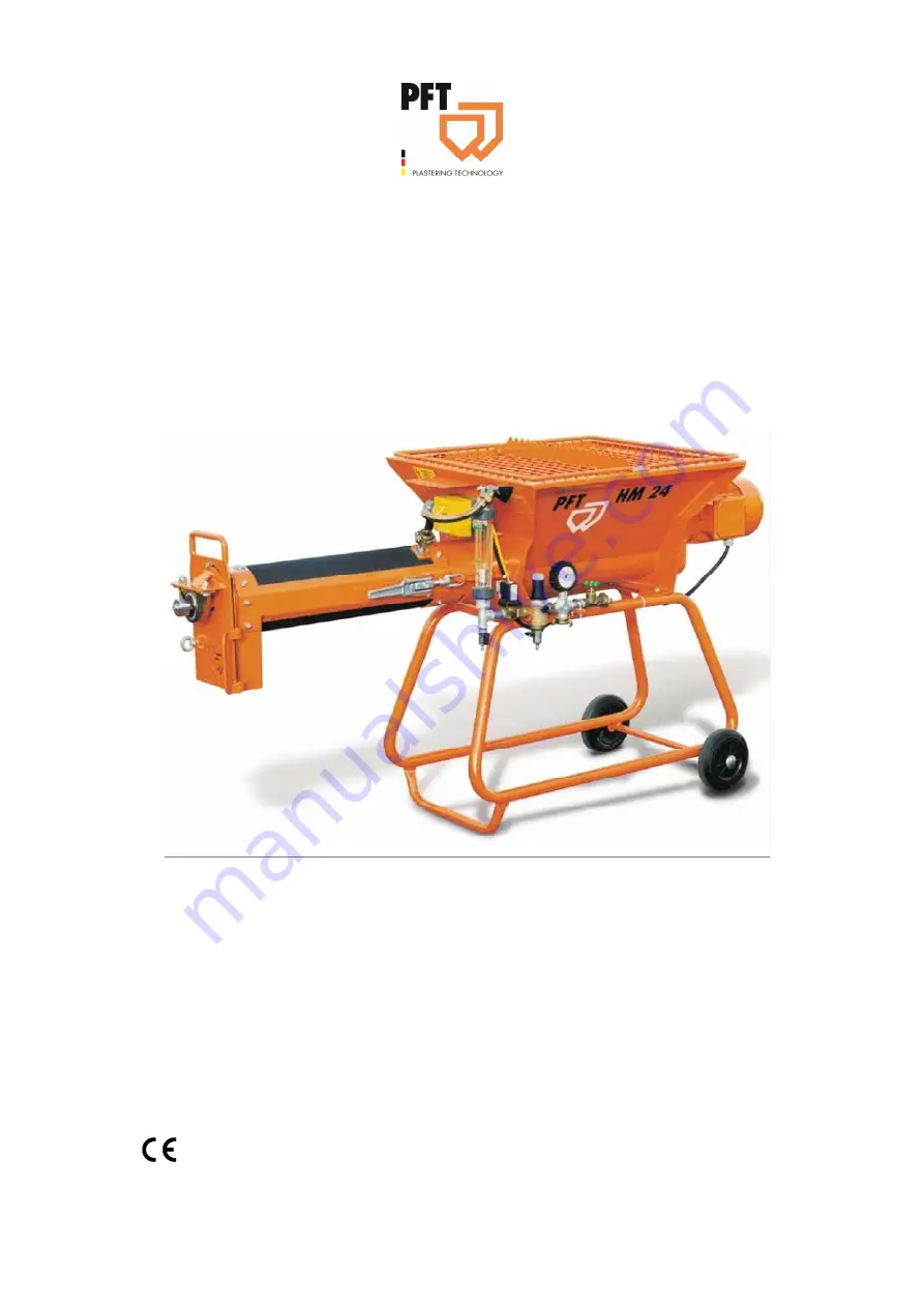
PFT SCREW MIXER HM 24 
Part 2, EC Declaration of Conformity 
Overview – Operation – Spare Parts Lists 


Article number of operating instructions:

 00 01 20 81


HM 24, 400V, 3 phases 60Hz item number 00211876 

HM 24, 400 V, 3 phases 60 Hz with AV 1000 and rubber mixing tube item number 00508157 

HM 24, 400 V, 3 phases 50 Hz item number 00007874 

HM 24, 230 V, 3 phases 60 Hz with rubber mixing tube item number 00265323 

HM 24, 400 V, 3 phases 50 Hz with rubber mixing tube item number 00020357 

HM 24, 400V with separate mortar outlet flange and dosing shaft 35 l/min item number 00008783 

HM 24, 400V, 3 phase, 50Hz with control box for level probe and vibrators item number 00036940 

HM 24, 400V, rubber mixing tube / control box / water pressure booster pump item number 00070219 

HM 24, 400V, rubber mixing tube, control box, water pressure booster pump item number 00463945 


Please read the operating instructions before starting work! 


Содержание HM 24

Страница 1: ...4 HM 24 230 V 3 phases 60 Hz with rubber mixing tube item number 00265323 HM 24 400 V 3 phases 50 Hz with rubber mixing tube item number 00020357 HM 24 400V with separate mortar outlet flange and dosing shaft 35 l min item number 00008783 HM 24 400V 3 phase 50Hz with control box for level probe and vibrators item number 00036940 HM 24 400V rubber mixing tube control box water pressure booster pump...

Страница 2: ... 07 Knauf PFT GmbH Co KG Postfach 60 97343 Iphofen Einersheimer Straße 53 97346 Iphofen Deutschland Telefon 49 9323 31 760 Telefax 49 9323 31 770 Technische Hotline 49 9323 31 1818 info pft iphofen de www pft eu ...

Страница 3: ...es 15 12 Transport packing and storage 15 12 1 Safety instructions for transport 15 12 2 Transport inspection 16 13 Packaging 16 14 Operation 17 14 1 Safety 17 15 Preparing the machine 18 16 Connecting the power supply 19 16 1 Power connection without control cabinet 19 16 2 Power connection with control cabinet 19 16 3 Check the individual connectors 19 17 Check the direction of rotation 20 17 1 ...

Страница 4: ...st Electrical Unit 400V 60Hz 44 26 17 Electrical Unit 230V 60Hz 45 26 18 Cable set HM 24 Art No 00002127 46 26 19 Support for mounted plug HM 22 24 2002 46 26 20 Control box HM 24 Art No 00008735 48 26 21 Water Manifold Unit Art No 00002119 00211923 50 26 22 Spare parts list Water Manifold Unit Art No 00002119 00211923 51 26 23 Water pressure booster pump HM 24 cpl Art No 00070238 52 26 24 Spare p...

Страница 5: ...according to Outdoor Directive 2000 14 EC Internal production control as per article 14 paragraph 2 in connection with annex V This declaration only refers to the machine in the state in which it has been placed on the market Parts subsequently added by the user and or subsequent interventions are not covered This declaration ceases to be valid if the product is converted or changed without consen...

Страница 6: ...efects are found in the safety devices or any other area that could impair safe operation the supervisor must be notified immediately For defects posing a hazard to persons the operation of the construction machine must be halted until the defect is eliminated 2 2 Periodic inspection Construction machines must be tested for safe operation by a specialist as the usage conditions and operating circu...

Страница 7: ...mmediate vicinity of the device so that it can be accessed easily by the personnel If the device is handed over to a third party please hand over the operating instructions document too The figures in this operating instructions document are not necessarily made to scale for better display and may deviate marginally from the actual design of the device 3 2 Please retain the instructions for later ...

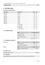
Страница 8: ...g Overall length 1870 mm Overall width 670 mm Overall height 970 mm Container volumev 110 Ltr 4 2 Electrical 400V Data Value Unit Voltage AC 60 Hz 400 V Voltage AC 50 Hz 400 V Current intake maximum 16 A Fuse Min 3 x 16 A 4 3 Operating conditions Environment Data Value Unit temperature range 2 45 C Relative humidity maximum 80 Duration Data Value Unit Maximum operating duration on piece 8 Hours 4 ...

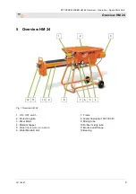
Страница 9: ...erview HM 24 1 2 3 12 11 10 9 8 7 6 5 4 Fig 1 Overview HM 24 1 ON OFF switch 2 Protection grille 3 Mixer Motor 4 Material hopper 5 Water input water connection 6 Water Manifold Unit 7 Frame 8 Water flow meter 100 1000 l h 9 Mixing tube 10 Rubber mixing tube 11 Mortar outlet flange 12 Bearing ...

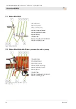
Страница 10: ...uge 5 Water Extraction Valve 6 Water Mains 7 Outlet Tap 8 Water Flow Meter 100 1000 l h 9 Water to Mixing Tube 5 2 Water Manifold with Water pressure booster pump 1 2 3 4 5 9 8 7 6 Fig 3 Water Manifold with Water pressure booster pump 1 Needle Valve 2 Soleniod Valve l 3 Pressure reducer 4 Water Pressure Gauge 5 Water Extraction Valve 6 Water Mains 7 Outlet Tap 8 Water Flow Meter 100 1000 l h 9 Wat...

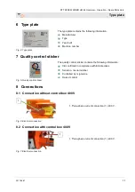
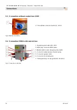
Страница 11: ...Fig 5 Quality control sticker The quality control sticker contains the following information CE confirmed in compliance with EU directives Serial no serial number Controlled by signature Date of control 8 Connections 8 1 Connection without control box 400V Fig 6 Electrical connection 1 Three phase current connection 1 400 V 8 2 Connection with control box 400V Fig 7 Electrical connection 1 Three p...

Страница 12: ...rrent connection 1 230 V 8 4 Connection HM 24 with control box Fig 9 Connection control box 1 Operation press button ON OFF 2 Blind plug connector KPS1 probe 3 Master switch is also emergency stop switch 4 Connection water pressure booster pump 5 Connection geared motor 6 Connection for vibrating unit 7 Yellow pilot lamp for wrong direction of rotation 1 2 3 7 6 5 4 1 ...

Страница 13: ...ne based on a modular concept Use the snaps to remove or fit on various dosing shafts and mixing tubes easily FOLLOW ALL MATERIAL MIXING INSTRUCTIONS FROM MORTAR MANUFACTURER The following terms and symbols are used in this manual to highlight important information NOTE Information for running the Machine efficiently WARNING Precautionary information for the prevention of accidents WARNING The mac...

Страница 14: ...nder the supervision of a qualified electrician and should comply with electro technical safety regulations 8 Observe all instructions for switching the machine on and off Watch display lamps for signals 9 When the machine is completely switched off for maintenance and repair work ensure that it cannot switch back on accidentaly Do this by switching off the main switch removing the key or by attac...

Страница 15: ...ansport within the company pay attention and observe the symbols and instruction on the package Use only the specified anchorage points Remove packaging only shortly before the assembly Suspended loads WARNING Danger to life from suspended loads When lifting heavy loads there is danger to life from falling parts or uncontrolled swinging parts Therefore Never step under suspended loads Observe the ...

Страница 16: ...aims can be filed only within the valid complaint periods Transportation of machine already in operation DANGER Danger of injury through mortar discharge Face and eyes can be damaged Perform the following steps before transportation 1 Pull out the main power cable first 2 Detach all other cable connections 3 Remove water supply line 4 Start transportation 13 Packaging On packaging The individual u...

Страница 17: ...aningfully and reused in many cases Hence Dispose of packaging material in an environment friendly manner Observe the locally applicable disposal specifications If necessary commission a specialized company to perform the disposal 14 Operation 14 1 Safety Personal protection equipment The following protective equipment must be worn while performing all jobs Work safety clothing Safety glasses Safe...

Страница 18: ...dent risks Increased noise level may cause permanent hearing deficiencies At close range of the machine 78 dB A can be exceeded due to operational conditions Close range is a distance of less than 5 metres to the machine 15Preparing the machine Prior to operating the machine carry out the following steps for preparing the machine Fig 10 Grille cover DANGER Rotating dosing shaft Risk of injury when...

Страница 19: ...e network 400V DANGER Danger of death from electric current The connection line has to be fused properly Connect the machine only to a power source with permissible RCCB 30 mA RCD residual current operated device type A 16 3 Check the individual connectors Fig 14 Power connections Connect water pump 1 NOTE The booster pump is necessary should the water pressure be less than 2 5 bar when the machin...

Страница 20: ...h can be switched back to zero but is disabled for the right position 17 2 On Off switch with phase inverter Fig 16 On Off switch with phase inverter Rotating field control All three phases are present and the rotating field is OK LED green lights up One phase is missing LED flashes red L1 is missing LED red flashes 1x fast L2 is missing LED red flashes 2x fast L3 missing LED red flashes 3x fast W...

Страница 21: ...ressor 3 from control cabinet WARNING Danger to life from rotating parts Improper operation may lead to serious damage to persons or property The respective drive motors must be operated only with the control cabinet of the machine 18 Setting Up the Machine Assemble the machine as follows Set up the hopper straight Insert the mixing shaft into the dosing shaft Mount mixing tube and secure it on th...

Страница 22: ... follow these steps Fill hopper Switch on the HM 24 at main switch Regulate the amount of water at the needle valve Mortar Consistency Adjust the needle valve in such a way that the machine emits trowel suited mortar at the mortar outlet NOTE Follow all material mixing instructions of the mortar manufacturer NOTE Interrupting Work The length of a break during operation will depend on the material ...

Страница 23: ...l the inlet strainer must be fitted with a filter strainer item no 00136619 bleed booster pump 19Putting the machine into operation 19 1 Hazardous dust WARNING Danger of health problems due to dust Inhaled dust can lead to long term lung damage or other health problems NOTE The machine operator or the person working in the dusty area must always wear a dust mask when filling the machine The decisi...

Страница 24: ... the following 5 steps When the hopper is 1 3 full reduce the water entry at the needle valve by a quarter Switch off the PFT HM 24 as soon as highly diluted mortar is discharged Remove the coupling of the power cable before disconnecting the mixing tube or else the safety hook on the machine will block the coupling Open the snaps on the mixing tube and remove it Release the mixing shaft and clean...

Страница 25: ...on the fittings block 4 Drain out water and shut the cocks again 22 Measures during power failure The PFT HM 24 is equipped with a restart lock After a power failures switch on the machine at the main switch for operation 23 Measures for Water Supply Failure In case of a water supply failure the PFT HM 24 will keep on running without mixing the material As soon as the fault is rectified the HM 24 ...

Страница 26: ...ts can execute uncontrolled movements and lead to serious injuries Hence Before starting work switch off the power supply and lock the switch against reactivation Environment protection Observe the following instructions on environment protection while performing maintenance jobs Remove discharged used up or excess grease from all lubrication points that are lubricated manually and dispose it in a...

Страница 27: ...l connectors hose connections and power cable connections 24 4 Dirt trapping sieve Check dirt trapping sieve in the water inlet daily 1 Take out dirt trapping sieve from the Geka coupling 2 Clean dirt trapping sieve 3 Replace sieve if there are thick dirt deposits 4 Reinsert dirt trapping sieve Dirt trapping sieve Geka coupling Article No 20152000 Remove and clean the dirt filter in the water inle...

Страница 28: ...sufficient free space before starting work Handle open sharp edged components carefully Pay attention to cleanliness and order at the workplace Components and tools lying loosely on each other or lying scattered are accident sources Dismantle components properly Consider the partially high dead weight of the components Use lifting tools if necessary Lock components so that they do not fall down or...

Страница 29: ...as remaining processing materials and dispose of them in an environment friendly manner 25 3 Disposal Recycle the dismantled components if no return or disposal agreement was signed Scrap metals Recycle plastic elements Dispose of the remaining components sorted by material quality CAUTION Environmental damages due to incorrect disposal Electrical scrap electronic components lubricants and other a...

Страница 30: ...EW MIXER HM 24 Overview Operation Spare Parts Lists Spare parts drawing 30 2017 08 07 26 Spare parts drawing 26 1 Hopper with Frame Unit 1 2 3 4 5 6 7 8 9 10 11 12 13 10 14 15 26 25 24 23 22 21 20 19 18 17 16 ...

Страница 31: ...screw M8 x 35 galv 10 4 20 20 86 04 Quick fastener with cap 16s x N 2 7 packing unit 10 pcs 11 2 20 70 58 02 Bolt A16 H11 x 50 12 2 20 20 99 21 Collar nut M16 13 2 20 20 85 00 Eye screw M16 x 80 galvanised 14 2 20 54 83 10 Wheel 180 x 50 x 90 15 2 20 20 86 03 Fastener with cap 20s x N 2 7 16 1 00 00 78 76 Frame HM 22 24 1 RAL2004 17 1 20 20 72 00 Safety nut M 8 galv 18 4 20 20 93 13 Washer B 8 4 g...

Страница 32: ...PFT SCREW MIXER HM 24 Overview Operation Spare Parts Lists Spare parts drawing 32 2017 08 07 26 3 Drive Unit Art No 00211876 ...

Страница 33: ...004 3 1 20 42 41 10 Motor connection cable 0 85m CEE plug 4x 16A 6h red loop 4mm 4 1 20 42 79 00 Plug CEE 4 x 16A 6h red 5 4 20 20 72 00 Safety nut M 8 galv 6 4 20 20 78 10 Hex screw M8 x 25 galv 7 1 00 01 01 60 Motor flange without protection bail HM 202 204 RAL2004 8 1 20 54 80 20 Gasket 200 x 190 x 10 D160 9 1 20 10 29 11 Hauling bracket with round funnel 25 mm boring HM 2 HM 200 10 1 20 20 96 ...

Страница 34: ...PFT SCREW MIXER HM 24 Overview Operation Spare Parts Lists Spare parts drawing 34 2017 08 07 26 5 Drive Unit 60Hz Art No 00265323 1 2 3 7 6 5 4 8 ...

Страница 35: ...0 42 92 99 Geared motor ZF21 3kw 274rpm RAL2004 3 1 00 01 01 61 Protection bail for motor adjustable for HM 202 204 RAL2004 4 1 00 02 20 86 CEE Panel mounted socket 4 x 16A 9h blue 5 1 20 54 80 20 Gasket 200 x 190 x 10 D160 6 1 20 10 29 11 Hauling bracket with round funnel 25 mm boring HM 2 HM 200 7 1 20 20 96 03 Threaded pin hex M8 x 20 galv 8 1 00 01 01 60 Motor flange without protection bail HM...

Страница 36: ...PFT SCREW MIXER HM 24 Overview Operation Spare Parts Lists Spare parts drawing 36 2017 08 07 26 7 Drive Unit 1 2 3 8 7 6 5 4 ...

Страница 37: ...0 42 41 10 Motor connection cable 0 85m CEE plug 4x 16A 6h red loop 4mm 3 1 20 42 79 00 Plug CEE 4 x 16A 6h red 4 1 00 00 21 10 Cover with flap HM 22 24 5 1 20 20 91 10 Spring washer B 12 galv 6 1 00 00 81 49 Hex screw M12 X 60 modified stainless 7 1 20 20 96 03 Threaded pin hex socket M8 x 20 galv 8 1 00 13 98 10 Hauling bracket Hm 22 24 galv cpl For spare parts orders only with specification of ...

Страница 38: ... MIXER HM 24 Overview Operation Spare Parts Lists Spare parts drawing 38 2017 08 07 26 9 Mixing Tube Unit Art No 00012594 1 2 3 4 5 6 7 8 9 10 11 12 13 33 32 31 30 29 28 27 26 25 24 23 22 21 20 19 18 17 16 15 14 ...

Страница 39: ...coupling 1 2 int thread 14 1 00 43 11 98 Sprocket mixing shaft HM 104 4 rows RAL2004 Art Nr 00070219 15 1 00 00 25 69 Dosing shaft HM 22 24 35l at 280rpm 16 1 00 02 14 95 Mixing shaft HM 2002 3 levels 17 1 20 54 76 00 Dowel pin 10 x 40 18 1 20 54 76 03 Dowel pin 6 x 40 19 1 00 01 25 92 Mortar output flange fixed to rubber mixing tube HM 2 RAL2004 20 1 00 01 94 21 Rubber front plate for mortar outp...

Страница 40: ...PFT SCREW MIXER HM 24 Overview Operation Spare Parts Lists Spare parts drawing 40 2017 08 07 26 11 Mixing Tube Unit HM22 24 Art No 00002116 1 2 3 4 5 6 7 8 9 10 11 18 17 16 15 14 13 12 ...

Страница 41: ...ce M14 7 2 20 20 85 22 Pin 8 H11 x 58 x 54 with washer and spline galv 8 2 20 20 99 92 Threaded pin hex socket M6 x 6 galv 9 1 20 02 60 01 Glide bearing with insert 10 1 20 02 60 02 Bearing bushing Thermoplast D60 x 40 11 1 20 54 82 10 Bearing bush HM 2 2000 2002 with bushing 12 1 00 01 99 67 Mixing shaft HM 2 22 24 2002 with scraper 13 1 20 54 76 00 Dowel pin 10 x 40 14 1 20 54 76 03 Dowel pin 6 ...

Страница 42: ...PFT SCREW MIXER HM 24 Overview Operation Spare Parts Lists Spare parts drawing 42 2017 08 07 26 13 Mixing Tube Unit Art No 20548520 1 2 3 4 5 6 7 8 9 15 14 13 12 11 10 ...

Страница 43: ...0 pcs 5 1 20 20 17 00 Gasket Geka coupling packing unit 50 pieces 6 1 20 20 16 50 Geka coupling dummy cover 7 1 20 54 81 05 Mixing tube HM 2 200 2002 RAL2004 8 1 20 55 29 10 Safety chain 2mm 250mm long K20 9 1 20 10 10 10 Splint D 4 5 with ring 10 1 20 54 55 01 Bearing with square bore and housing 11 2 20 20 68 01 Hex screw M12 x 30 galv 12 1 20 54 55 06 Bearing with square bore 13 1 00 04 13 96 H...

Страница 44: ...61 00 Hex screw M8 x 20 galv 3 2 20 20 93 13 U disc B 8 4 galv 4 2 20 20 72 00 Nut M8 galv 5 2 20 20 62 03 Nut M4 galv 6 2 20 20 63 05 Cylindrical screw M4 x 12 galv 7 1 00 21 24 19 Cable set HM24 400V 60Hz 8 1 00 45 64 61 Plug solenoid valve 400V 50 60Hz 9 1 00 04 11 41 Skintop screwed joint M16 x 1 5 10 2 00 04 11 42 Skintop screwed joint M25 x 1 5 11 1 00 21 18 78 On Off switch with phase chang...

Страница 45: ...2017 08 07 45 26 17 Electrical Unit 230V 60Hz 1 2 Item Qty Art No Description 1 1 20 45 69 46 On Off switch with motor protection 10 16 A 230 V 60 Hz 2 1 00 02 20 80 CEE connection plug phase inverter 5 x 16A 9h blue For spare parts orders only with specification of the type plate ...

Страница 46: ...R HM 24 Overview Operation Spare Parts Lists Spare parts drawing 46 2017 08 07 26 18 Cable set HM 24 Art No 00002127 1 2 3 4 5 6 7 8 9 26 19 Support for mounted plug HM 22 24 2002 10 10 11 10 12 13 12 13 1 2 3 4 9 8 ...

Страница 47: ...plug HM 22 24 2002 5 1 00 00 12 28 On Off switch with phase changing device 6 5 10A 6 1 00 04 11 41 Connector skintop with nut M16 x 1 5 7 1 00 00 21 27 Cable set HM 24 8 2 00 02 20 63 Plug solenoid valve 9 2 20 15 26 12 Gasket solenoid coil type 280 10 3 00 04 11 42 Skintop screwing M 25 x 1 5 11 1 00 02 20 75 CEE plug 5 x 16A 6h 12 4 20 20 62 03 Safety nut M4 galv 13 4 20 20 63 05 Cheese head sc...

Страница 48: ...24 Overview Operation Spare Parts Lists Spare parts drawing 48 2017 08 07 26 20 Control box HM 24 Art No 00008735 1 2 3 4 5 6 25 24 23 22 21 18 14 16 20 19 18 17 16 7 8 9 10 11 12 13 14 15 35 34 34 33 32 31 30 29 28 27 26 ...

Страница 49: ...16 2 00 05 38 34 Fastening adapter M 22 17 1 00 05 38 31 Membranes angular for double pressure switch M22 TDD 18 1 00 05 38 81 Luminous element white 12 30V 19 1 00 05 38 36 Contact element 1 break contact M 22 20 1 00 05 38 74 Front cap for the signal lamp yellow M 22 21 1 20 44 45 00 Key for control box 22 1 00 03 62 49 Lock for control box 23 1 00 04 31 13 Door HM 104 RAL7032 24 2 00 05 37 67 H...

Страница 50: ...iew Operation Spare Parts Lists Spare parts drawing 50 2017 08 07 26 21 Water Manifold Unit Art No 00002119 00211923 1 2 3 4 5 6 7 8 9 10 11 12 22 11 16 23 21 13 14 15 16 7 17 18 19 20 21 22 34 33 32 31 13 30 29 28 27 26 25 24 5 ...

Страница 51: ...xt thread with gasket 15 1 20 21 52 00 Tap 1 2 without drainer 16 2 20 20 34 01 Double nipple 1 2 X 60mm galv 17 3 20 20 99 86 Steel bow M8 X 1 18 1 00 00 21 21 Support for water manifold HM 22 24 19 1 20 15 20 00 Water inlet filter for Geka coupling 20 1 00 00 15 58 Pressure reducer D 06F 1 2 21 2 20 20 31 07 Nipple 1 2 ext thread flat with nut 3 4 22 2 20 21 53 00 Tap 1 4 ext thread with socket ...

Страница 52: ...PFT SCREW MIXER HM 24 Overview Operation Spare Parts Lists Spare parts drawing 52 2017 08 07 26 23 Water pressure booster pump HM 24 cpl Art No 00070238 1 2 3 4 5 4 6 7 14 13 12 8 9 10 11 19 18 17 16 15 ...

Страница 53: ... 36 20 Curved section 1 int thread ext thread galv 8 1 00 23 13 67 Water pressure booster pump SL AV3 PK a 37kW 230V 9 4 20 20 71 03 Hex screw M6 x 20 galv 10 4 20 20 93 00 Washer B 6 4 galv 11 4 20 20 62 00 Safety nut M6 galv 12 4 20 20 99 86 Steel bow M8 X 1 13 2 20 20 72 00 Safety nut M8 galv 14 1 00 00 97 69 Support for AV 3 at HM 22 24 15 1 20 15 20 00 Water inlet filter for Geka coupling 16 ...

Страница 54: ...PFT SCREW MIXER HM 24 Overview Operation Spare Parts Lists Spare parts drawing 54 2017 08 07 26 25 Water pressure booster pump AV1000 HM 24 Art No 00466201 1 2 3 9 8 7 6 5 14 13 4 12 11 10 ...

Страница 55: ...al 5 1 00 27 19 87 Ball tap 1 8 Internal thread external thread one side lever 6 1 20 56 53 27 Copper gasket D 10 5 7 1 00 49 30 84 Water pressure booster pump AV1000 1 230V 1Phase 50Hz 8 1 00 46 62 03 Support AV1000 1 HM 22 24 RAL2004 9 1 20 42 41 43 Motor connection cable 0 8m Schuko plug and cable lug 10 1 20 21 36 08 Water air hose 3 4 x 750mm 11 2 20 20 29 00 Hose clip 28 31 packing unit 10ST...

Страница 56: ...MIXER HM 24 Overview Operation Spare Parts Lists Spare parts drawing 56 2017 08 07 26 27 Spare parts list AV1000 1 400V 60Hz Art No 00491839 1 2 3 4 5 6 7 8 9 27 26 25 24 23 22 10 11 12 13 14 15 16 17 18 19 20 21 ...

Страница 57: ...n request Grooved ball bearing 12 1 On request Shaft with rotor 13 1 On request Grooved ball bearing 14 1 On request Arrester 15 1 On request Motor housing with winding 230 400V 16 1 On request Support foot 17 1 On request Bearing cover front 18 3 On request Screw 19 1 On request Cover pump body 20 1 On request O ring for pump body 21 1 00467107 Face seal for AV 1000 22 1 On request Wheel und Diff...

Страница 58: ...PFT SCREW MIXER HM 24 Overview Operation Spare Parts Lists Circuit Diagramm 60Hz 58 2017 08 07 27 Circuit Diagramm 60Hz ...

Страница 59: ...PFT SCREW MIXER HM 24 Overview Operation Spare Parts Lists Circuit Diagramm Cable set 00002127 2017 08 07 59 28 Circuit Diagramm Cable set 00002127 ...

Страница 60: ...PFT SCREW MIXER HM 24 Overview Operation Spare Parts Lists Circuit Diagramm HM 24 S163754C 60 2017 08 07 29 Circuit Diagramm HM 24 S163754C ...

Страница 61: ...PFT SCREW MIXER HM 24 Overview Operation Spare Parts Lists Circuit Diagramm HM 24 230 V 3 phases 60 Hz 2017 08 07 61 30 Circuit Diagramm HM 24 230 V 3 phases 60 Hz ...

Страница 62: ...PFT SCREW MIXER HM 24 Overview Operation Spare Parts Lists 62 2017 08 07 ...

Страница 63: ...PFT SCREW MIXER HM 24 Overview Operation Spare Parts Lists 2017 08 07 63 ...

Страница 64: ...ists 64 2017 08 07 PFT THE FLOW OF PRODUCTIVITY Knauf PFT GmbH Co KG Postfach 60 97343 Iphofen Einersheimer Straße 53 97346 Iphofen Deutschland Telefon 49 9323 31 760 Telefax 49 9323 31 770 Technische Hotline 49 9323 31 1818 info pft iphofen de www pft eu ...

Отзывы: