background image

Содержание POWERLINE 3741

Страница 1: ...296 12 19 008 002 Betriebsanleitung engl 06 12 DOKU SEAM SYSTEM 3741 3745 ...

Страница 2: ... of PFAFF Instruction Manuals whether in whole or in part is only permitted with our previous authorization and with written reference to the source PFAFF Industriesysteme und Maschinen AG Hans Geiger Str 12 IG Nord D 67661 Kaiserslautern ...

Страница 3: ...unctions 16 2 03 02 Operating modes 17 2 03 03 Tools 17 2 04 Creating seam programs 18 2 04 01 Sewing parameter input 22 2 04 02 Input of action at beginning of seam sector 23 2 04 03 Input of end of seam sector 24 2 04 04 Input of action at end of seam sector 25 2 04 05 Thread force 27 2 05 Service 29 2 06 Cold start 30 2 07 Users rights 31 2 08 Backup restore 33 2 09 Label editor 35 2 10 Definin...

Страница 4: ...inding the bobbin thread regulating the winder tension PFAFF 3745 PREMIUM 55 3 07 06 Bobbin changing threading and regulating the bobbin thread tension 56 3 07 07 Threading the needle thread PFAFF 3741 PLUS 3745 PLUS 57 3 07 08 Threading the needle thread PFAFF 3745 PREMIUM 58 3 08 Sewing 59 3 08 01 Calling up carry out the sewing operation without camera for bobbin thread monitor 59 3 08 02 Calli...

Страница 5: ...e opener 85 4 05 10 Bobbin winder 86 4 05 11 Thread check spring and thread regulator 87 4 05 12 Sewing foot pressure 88 4 05 13 Lubrication 89 4 05 14 Reengaging the slip clutch 90 4 06 Adjusting the thread trimmer 900 81 91 4 06 01 Resting position of the roller lever radial position of the control cam 91 4 06 02 Position and height of the thread catcher 92 4 06 03 Knife pressure 93 4 06 04 Bobb...

Страница 6: ...ference position 121 5 02 02 Check adjust the trigger signals 122 5 02 03 Check the zero position of the monitor power signal 123 5 02 04 Checking the setting of the sewing head 124 5 02 05 Recording the characteristic thread strength curve 124 5 03 Checking the calibration calibration result 127 Register 06 127 6 Circuit diagrams 129 6 01 Pneumatics switch diagram PFAFF 3741 3745 129 6 02 Block d...

Страница 7: ...Register 01 ...

Страница 8: ......

Страница 9: ...g sewing tools e g needle roller presser needle plate and bobbin when threading the machine when leaving the machine unattended and during mainte nance work the machine is to be separated from the power supply by switching off the On Off switch or by removing the plug from the mains Everyday maintenance work is only to be carried out by appropriately trained personnel Repairs and special maintenan...

Страница 10: ...ing personnel at all times The Instruction Manual must be read before operating the machine for the first time The operating and specialist personnel is to be instructed as to the safety equipment of the machine and regarding safe work methods It is the duty of the user to only operate the machine in perfect running order It is the obligation of the user to ensure that none of the safety mechanism...

Страница 11: ...ges in the machine which may limit its safety 1 05 02 Specialist personnel Specialist personnel are persons with a specialist education in the fields of electrics electro nics and mechanics They are responsible for the lubrication maintenance repair and adjust ment of the machine The specialist personnel is obliged to observe the following points and must always observe the Notes on Safety in the ...

Страница 12: ...cts may be trapped or flung out of the machine Do not run the machine without finger guard 1 Danger of injury by up and down movement of needle Do not run the machine without take up lever guard 2 Danger of injury by moving take up lever Do not run the machine without belt guards 3 and 4 Danger of injury by rotating v belt Do not operate the machine without tilt lock 5 Danger of crushing between s...

Страница 13: ...cal documents The operating and qualified personnel must be appropriately authorised to handle the machine i e qualified and instructed The operator promises to train his personnel accordingly Furthermore the user have to take care to calibrate the machine when the control box or the thread force sensor was changed We hereby confirm that we have read and understood the documentation for the PFAFF ...

Страница 14: ......

Страница 15: ...Register 02 ...

Страница 16: ......

Страница 17: ...This instruction manual applies to machines from software version 1 8 and serial number 2 763 625 onwards Kurzanleitung zur Eingabe engl 06 12 SHORT INSTRUCTIONS FORTHE INPUT 3741 3745 ...

Страница 18: ... previously entered limit values and issues an evaluation of the seam on the touch screen monitor If the seam is a good seam an appropriate signal is given to the PC interface and a label can be printed which can then be attached to indicate the appropriate quality of the seam The label can be designed individually with an editor The docu seam system also activates a missed stitch recognition func...

Страница 19: ...n Production Pop ups Error Warning Info display Switch to Manual interruption Manual sewing Test seam Work instructions Winding Popups Settings Seam program creation Work instructions Label editor Users and rights Equipment interfaces Backup and restore Evaluation and printing Parameterization Service Calibration Cold start Inputs outputs Feed regulator configuration Thread force Drives Sensors Ver...

Страница 20: ... struction Manual Help mode After calling up the help mode the next function selected is described Online help After activation of the help module the online help can be called up including language and document selection Confirm The selection is confirmed entered or altered values are saved Stop The selection process is cancelled entered or altered values are not saved Back The superordinate leve...

Страница 21: ...oration see Chapter 2 08 Back up Restore Evaluation and print function A selected docu seam with all relevant values is displayed Label editor A menu is called up for editing labels see Chapter 2 09 Label editor 2 03 02 Operating modes Selecting and configuring seam programs Functions for selecting processing and creating seam programs are called up see Chapter 2 04 Creating seam programs Tools A ...

Страница 22: ...es of how to create a seam program Select a seam program from the list Edit an existing seam program or Select a seam program from the list Copy a seam program to create a new seam program on the basis of an existing one or Create a new seam program or Deleting a seam programme 20 06 2006 20 06 2006 23 07 2006 24 07 2006 Industrial ...

Страница 23: ... the second stitch length can be called up with the appropriate key on the machine head Enter change the value for the second stroke can be called up with the appropriate key on the machine head Enter top thread and bobbin thread ID in input field 3 or scan in via hand scanner to activate this function later in input field 4 Control will then only accept sewing material with that ID 4 Material 1 1...

Страница 24: ... the end label value 1 print label each time value 10 print label every tenth time Select seam section from sector 1 If necessary delete selected seam section If necessary insert seam section after the selected seam section With function 2 specify the following for the selected seam sector Activate deactivate docu seam sector Activate deactivate missed stitch recognition function Activate deactiva...

Страница 25: ...of the seam sector and if necessary enter change the appropriate values see Chapter 2 04 03 Input of end of seam sector Call up the menu for entering the action at the end of the seam sector Depending on the action selected the symbol may be different In this example the condensed end stitch es action is selected Select the action and if necessary enter the label number see Chapter 2 04 04 Input o...

Страница 26: ...ched on or off for the current seam sector If the function is switched on the needle moves to the top position when sewing stops Foot raised at stop This function is switched on or off for the current seam sector If the function is switched on the foot is raised when sewing stops Sew in label only after a docu seam area This function is switched on or off for the current seam sector If the functio...

Страница 27: ...mber of forward stitches in sector 6 and the number of reverse stitches in sector 7 the double start bartack at the beginning of the seam sector is sewn with the corresponding values Condensed start stitches After the selection of this function and the input of the values for the stitch length and the number of stitches the condensed stitches at the beginning of the seam sector are sewn with the c...

Страница 28: ...corresponding number of stitches have been sewn End of seam sector by seam length After function 4 has been selected and following the input of the value for the seam length the end of the seam sector is started after the corresponding seam length has been sewn End of seam sector by sensor with stitch counting After function 5 has been selected and following the input of the values for the maximum...

Страница 29: ...he values for the tack speed the number of forward stitches and the number of reverse stitches the double end bartack is sewn at the end of the seam sector with the corresponding values Condensed end stitches currently active After the selection of this function 4 and the input of the values for the stitch length in sec tor 5 and the number of stitches in sector 6 the condensed stitches at the end...

Страница 30: ... sector 7 Label payout The number of labels to be printed can be selected in range 8 Scan label This function is switched on or off for the current seam sector If the function is switched on the label must be scanned Conclude the input The input is concluded by taking over the selection and the entered values Stop the input The input is concluded without taking over the selection and the entered v...

Страница 31: ...his value must never be ex ceeded Hard bottom limit The limit value is entered in sector 2 In the docu seam area the value must never be lower than this limit Bottom limit for missed stitch recognition The limit value is entered in sector 3 If the value falls below this limit a missed stitch is recognised 450 400 150 20 200 3 Fadenkraft 1 2 3 4 6 7 PFAFF 3741 PLUS PFAFF 3745 PLUS 450 400 150 20 20...

Страница 32: ...es The number of tolerance stitches is entered in sector 7 The number of tolerance stitches is used to define how often the thread strength within the docu seam area may exceed or drop below the soft limits Thread tension control only on the PFAFF 3745 PREMIUM Pressing the button 8 deactivates the function Thread tension control during sewing button 9 reactivates the function Pressing button 10 ac...

Страница 33: ...menu Inputs outputs After this function has been selected the machine s inputs are displayed Outputs can set and reset manually The pedal function can be checked Drives After this function has been selected the motor functions can be checked and the value for the motor reference position altered Feed regulator configuration After this function has been selected the feed regulator can be configured...

Страница 34: ...ee chapter 4 07 03 in the settings manual Camera For camera commissioning please see chapter 4 07 04 in the settings manual 2 06 Cold start When a cold start is carried out all altered parameter for the sewing head are deleted and set back to default values status at the time of delivery Log in as administrator Select the tools function Select the cold start function ...

Страница 35: ...e On delivery of the machine the user ID pfaff must be entered Any number of users can be added and or edited The rights of individual users are defined by allocating the users to relevant user groups User groups Administrator Supervisor Operator Guest Only the administrator can create and edit users and assign users to specific user groups Log in as administrator Select the tools function Call up...

Страница 36: ...am can be ended Label copy can be created Manual seam interruption can be switched on Test seam mode can be activated Seam programme can be activated Production can be interrupted Seam programme can be created Docu seam error can be ignored ...

Страница 37: ... Place a checkmark next to the relevant window in order to allow the backup to proceed at the specified time and date The PC associated with the machine must be switched on at the set backup time In order to revert to a previous status select the function Restore Select the relevant directory containing backup data and start the restore process Max data base size and monitoring mode setting in win...

Страница 38: ...Input 34 Daten base explorer Shows the data base content Daten base setting Select your data base type and the data base connection see window 3 and 4 3 4 ...

Страница 39: ...tion 5 The label element is shown as a preview If necessary edit the selected label element with function 6 If necessary change the size of the selected label element with function 7 After tapping box 8 enter the text for the selected label element If necessary select variables time date counter etc for the selected label element with function 9 If necessary change the font of the selected label e...

Страница 40: ...Select the desired picture file with function 14 The picture appears as a preview The picture element can be shifted as described above and the size changed Carry out a test print out of the label by selecting function 15 Save the changes and quit the label editor function The entry mode deactivated without applying the selection Hochformat 46 90 Industrial 13 14 15 ...

Страница 41: ...e entry window 1 for top and bobbin threads Input relevant material by entering the barcode material number and material type in the entry window 2 If no thread and material are selected any type of thread or material can be used If material and thread were selected only the selected items can be used Input label printer in window 3 Input label printer in window 4 Define print process for protocol...

Страница 42: ...Change needle will be displayed a re set of the actual value will re start the count 6 7 A daily or weekly parts counter can be specified in window 8 The counter start value can be entered in window Actual value 8 Relevant machine equipment must be selected in window 10 Selecting 3741 will suppress functions 10 11 The programme will have to be restarted after any changes 9 ...

Страница 43: ...Register 03 ...

Страница 44: ......

Страница 45: ...This instruction manual applies to machines from software version 1 8 and serial number 2 763 625 onwards Betriebsanleitung engl 06 12 INSTRUCTION MANUAL 3741 3745 ...

Страница 46: ...e PFAFF 3745 PLUS is a workplace with a single needle lockstitch special high speed sewing machine with unison feed mechanical tensioning a mechanical bobbin winder and a large hook and docu seam system The machines are used for sewing lockstitch seams in fields requiring safety seams e g in the automotive industry Any and all uses of this machine which have not been approved of by the manufacture...

Страница 47: ... height 120 mm Bed plate dimensions 640 x 200 mm Ambient temperature 85 rel humidity condensation not permitted 5 40 C Noise data Noise emission level at workplace with a sewing speed of 2400 spm LpA 80 dB A Noise measurement in accordance with DIN 45 635 48 A 1 ISO 11204 ISO 3744 ISO Motor data See name plate on motor Air consumption per switch cycle 0 146 NI Net weight of sewing head approx 72 k...

Страница 48: ...and various plastic materials The electrical equipment comprises plastic materials and copper The machine is to be disposed of according to the locally valid pollution control regula ti ons if necessary a specialist ist to be commissioned Care must be taken that parts soiled with lubricants are disposed of separately according to the locally valid pollution control regulations ...

Страница 49: ... the machines are only transported in an upright position 3 04 03 Disposal of packing materials The packing materials of this machine comprise paper cardboard and VCE fibre Proper dis posal of the packing material is the responsibility of the customer 3 04 04 Storage If the machine is not in use it can be stored as it is for a period of up to six months but It should be protected against dust and ...

Страница 50: ...instruction manual work to be carried out or important information is accentuated by symbols These symbols have the following meanings Note information Cleaning care Lubrication Maintenance repairs adjustment service work only to be carried out by technical staff ...

Страница 51: ...y operating switch 1 Switch 2 regulates the brightness of the sewing lamp 128 0 3 06 02 Power bar Switch 1 is used to switch the complete power supply of the PC components PC touch screen monitor hand held scanner printer etc on or off If an individual device is not activated after the power bar has been switched on please check if the switches of the in dividual devices are activated Fig 6 02 1 3...

Страница 52: ...imum level of the oil supply has been reached When the keys 1 8 are operated the functions listed below are carried out Key 1 The functions of the keys 2 7 can be allocated to this key To program key 1 simultaneously press one of the keys 2 7 and key 1 for approx 3 seconds The function of the selected key is taken over and the yellow LED in this key lights up Key 2 Reverse sewing or intermediate b...

Страница 53: ...ression all tacks switched off 3 reverse move to needle position stepby step 4 Edge trimmer on off 5 programmable tack on off Key 6 Calling up the pre selected stitch length Diode on 2nd stitch length diode off standard stitch length Key 7 Threading aid Needle rises without thread trimming thread clamp is opened thread tension is released and the motor start inhibitor is activated If the key is op...

Страница 54: ...Pedal With the on off switch on 0 Machine stop 1 Sew 1 Raise presserfoot 2 Trim thread on machines with thread trimmer Fig 6 04 Fig 6 05 3 06 05 Lever for lifting the presser foot The sewing foot can be lifted by raising lever 1 1 ...

Страница 55: ...6 06 1 3 06 07 Bobbin thread supply monitor When the residual thread amount is reached symbol lamp A flashes After the next thread trimming action a corresponding message is shown on the touch screen monitor After the bobbin has been changed and the message acknowledged the operating process can be continued Fig 6 07 A ...

Страница 56: ... are carried out on the touch screen monitor The appropri ate operating mode messages parame ters etc are displayed Fig 6 09 128 024 3 06 08 Adjustment of the stand height optional The stand height can be adjusted by ope rating switch key 1 accordingly Fig 6 08 1 ...

Страница 57: ... of the hand held scanner af ter pressing key 1 it is possible to read user and process data For example the user log in the input of material needle thread and bobbin thread data can be car ried out with the hand held scanner Fig 6 11 1 3 06 12 PC Never switch off the PC if the PC has not been shut down completely Danger of data loss ...

Страница 58: ...ower bar and wait until the PC has started Tap on the input box 1 A box for entering the user appears Enter user Confirm input If the user has an ID card with appropriate barcode alternatively the user can be entered with the use of the hand held scanner 3 07 02 Language selection Carry out the log in Call up the menu for language selection Select the desired language flag The selected language is...

Страница 59: ...ing Only use needles from the sys tem intended for the machine see Chapter 3 Specifications Activate the threading aid on the machine head by pressing the key Loosen screw 1 Insert the needle as far as possible The long needle groove must be facing left Tighten screw 1 Switch off the threading aid on the machine head again by pressing the key Fig 7 03 1 ...

Страница 60: ...he thread is retained Place empty bobbin 4 on the bobbin winder spindle To switch on the bobbin winder push up lever 6 The bobbin is wound during sewing The bobbin winder stops automatically when the bobbin 4 is filled sufficiently Remove full bobbin 4 and cut off the thread in thread clamp 3 The tension of the thread on bobbin 4 can be adjusted on the bobbin winder tension unit 2 The volume of th...

Страница 61: ... up lever 6 to switch on the bobbin winder Enter or scan in the bobbin number If no thread classification is required enter the value 0 After the bobbin number has been entered the bobbin winder starts automatically and stops again when bobbin 4 has been filled sufficiently Remove the full bobbin 4 and break off the thread in the thread clamp The tension of the thread on bobbin 4 can be set on the...

Страница 62: ...is pulled Turn down latch 1 Pull the thread through slot 2 to pull beak 3 into hole 4 Call up the tools function Call up the service menu Select the Thread force function Thread the bobbin thread through the sensor as shown in Fig 7 06a and pull it through evenly Compare the displayed value with the standard value and if necessary adjust the bobbin thread tension accordingly with screw 6 Close the...

Страница 63: ...f the machine suddenly starts running Activate the threading aid on the machine head by pressing the key Thread the needle thread as shown in Fig 7 07 Switch off the threading aid on the machine head again by pressing the key 3 07 07 Threading the needle thread PFAFF 3741 PLUS 3745 PLUS Fig 7 07 2 1 ...

Страница 64: ...ury if the machine suddenly starts running Activate the threading aid on the machine head by pressing the key Thread the needle thread as shown in Fig 7 08 Switch off the threading aid on the machine head again by pressing the key 3 07 08 Threading the needle thread PFAFF 3745 PREMIUM Fig 7 08 ...

Страница 65: ...rk must have been carried out see Chapter 7 Setting up 3 08 01 Calling up carry out the sewing operation without camera for bobbin thread monitor After the user s log in following steps must be carried out Call up the seam program selection function Select the desired program from the list As an alternative to the manual seam program selection the appropriate seam program can also be selected with...

Страница 66: ... function Select the desired program from the list The following message will be displayed on the monitor Industrial 1 Default Programm 20 06 2006 000 Manual 29 03 2012 001 Unterfaden Kamera 04 04 2012 998 Doku Test 29 03 2012 999 Test Seam 17 02 2012 Move bobbin cover 1 into reading position by retracting to spring plate 2 Confirm position 1 2 Warnung Spulenabdeckung in Leseposition bringen ...

Страница 67: ...g the pedal A green bar above the image means reading process is under way Turn bobbin as needed to allow reading of DATA Matrix code A red bar above the image means reading process is not under way camera error or bobbin cover 1 not in reading position Warnung Spulenabdeckung offen Close bobbin cover 1 ...

Страница 68: ...1 3745 PLUS Call up the seam program selection function 20 06 2006 20 06 2006 23 07 2006 24 07 2006 Industrial Select the desired program from the list Call up the production function Industrial Call up the function Trial Seam Insert the material Create a trial seam ...

Страница 69: ...63 Set the adjustment nut 1 with an Allen key 2 so that the upper thread tension is set to the median value of the monitoring range Fig 8 01 2 1 The new value is stored by pressing the button Trial Seam again ...

Страница 70: ...45 PREMIUM Call up the seam program selection function 20 06 2006 20 06 2006 23 07 2006 24 07 2006 Industrial Select the desired program from the list Call up the production function Industrial Call up the function Trial Seam Insert the material Create a trial seam ...

Страница 71: ...t the value for the upper thread tension via the arrow keys 1 so that the upper thread tension is set to the median value of the monitoring range The new value is stored by pressing the button Trial Seam again 10 1 ...

Страница 72: ...titch detection Edge guide recognition optional Thread force After this function has been selected the values for the set limit values of the thread strength and the tolerance range for missed stitches are shown Sewing parameters After this function has been selected the sewing parameters are displayed The sewing pa rameters are specified during the seam program input see Short Instructions for th...

Страница 73: ... for selecting the operating mode Back This function is used to call up the last level Display of the sewing results In sector 5 both the number of good ok and bad nok seams are displayed Manual interruption The seam cycle is interrupted To continue the seam program the seam sector can be re se lected Manual sewing Sewing takes place without fixed seam sectors The characteristics of the thread str...

Страница 74: ...Sewing 68 3 08 06 Concluding the sewing operation To end the sewing operation call up the next level Shut down the PC Switch off the machine on the power bar and at the main switch ...

Страница 75: ...be disconnected from the mains by switching off the on off switch or by removing the mains plug Danger of injury if the machine suddenly starts up To avoid breakdowns the following cleaning work is recommended for single shift ope ration Open the bed slide and remove the bob bin Clean the hook and hook compartment daily several times if in continuous use Set the bobbin in position and close the be...

Страница 76: ...nsor When the minimum oil level is reached key 3 on the machine head shines red If required fill oil into the tank through hole 1 Oil level indicator 2 must not exceed the MAX marking Only use oil with a medium viscosity of 22 0 mm s at 40 C and a density of 0 865 g cm at 15 C We recommend PFAFF sewing machine oil part No 280 1 120 144 3 09 03 Lubricating Fig 9 02 1 2 3 ...

Страница 77: ...ir hose is disconnected from the air filter regulator Cleaning the filter Unscrew water bowl 1 and take out fil ter 2 Clean the filter with compressed air or with isopropyl alcohol part number 95 665735 91 Screw in filter 2 and screw on water bowl 1 3 09 04 Checking regulating the air pressure Check the air pressure on gauge 1 every time before operation Gauge 1 must show a pressure of 6 bar Regul...

Страница 78: ...loads As an alternative to the internet download the parts lists can also be ordered in book form under part no 296 12 19 008 System 134 35 91 500 251 05 PFAFF 3741 3745 PLUS 91 510 041 05 PFAFF 3745 PREMIUM 91 500 460 05 11 174 082 15 11 108 093 25 91 500 118 01 900 81 11 225 172 15 91 500 399 05 11 130 173 25 91 500 397 05 91 501 505 05 11 130 089 15 2x 11 130 173 15 2x 11 225 223 25 2x 11 108 1...

Страница 79: ...92 25 2x 91 501 022 05 11 130 092 25 ø 26 91 510 164 05 91 501 028 15 91 501 029 15 91 510 140 91 91 510 141 91 91 501 020 15 3x 91 501 031 05 11 250 078 15 91 501 034 05 11 330 280 15 2x 11 130 092 25 2x 91 501 033 05 11 130 092 25 91 510 045 04 ø 32 2 91 510 139 04 2 91 501 027 05 91 501 037 05 2 Marking dots strokes or numbers to be stated on order PFAFF 3745 PREMIUM ...

Страница 80: ...AFF 3745 PLUS 91 501 026 05 91 501 028 15 91 501 029 15 91 501 017 91 91 501 030 91 91 501 020 15 3x 91 501 031 05 11 250 078 15 91 501 034 05 11 330 280 15 2x 11 130 092 25 2x 91 501 033 05 11 130 092 25 91 501 037 05 ø 26 91 501 288 05 ...

Страница 81: ...Register 04 ...

Страница 82: ......

Страница 83: ...This instruction manual applies to machines from software version 1 8 and serial number 2 763 625 onwards Justieranleitung engl 06 12 ADJUSTMENT MANUAL 3741 ...

Страница 84: ...rresponds to the most logical work sequence for machines which have to be completely adjusted If only specific individual work steps are carried out both the preceding and following chapters must be observed Screws nuts indicated in brackets are fastenings for machine parts which must be loosened before adjustment and tightened again afterwards 4 02 Tools gauges and other accessories for adjusting...

Страница 85: ...ance wheel adjustment aid Requirement When the needle bar is positioned at t d c the marking 0 on the scale should be level with the top edge of the belt guard see arrow Adjust the scale dial 1 depending on model screws 2 or 3 in accordance with the re quirement Fig 4 01 1 2 2 3 3 ...

Страница 86: ...ition of recess 8 3 A gap of 0 3 mm should exist between initiator 5 and switching plate 4 Turn machine on stitch platen motor moves to reference position Turn shaft 1 of the stitch platen screws 2 and 3 in accordance with requirement 1 Move switching plate 4 in accordance with rule 3 and tighten screws 2 Set bolt 6 of lever 7 to the middle of recess 8 and tighten screws 3 Check rule settings and ...

Страница 87: ...d needle feed Requirement Bottom transporters as well as the needle bar should not move when stitch platen 3 is activated with handwheel at 190 or higher Adjust eccentric 1 screws 2 in accordance with the requirement Make sure that the cut out see arrow is visible 1 2 3 ...

Страница 88: ...80 Fig 4 04 4 05 04 Feeding motion of the bottom feed dog Requirement When the balance wheel is positioned at 180 the feed dog should be at t d c Adjust eccentric 1 screws 2 in accordance with the requirement 1 2 ...

Страница 89: ... by moving crank 6 nut 7 up or down Fig 4 05 0 5 mm 1 2 3 4 5 2 4 127 091 7 6 4 05 05 Height of the bottom feed dog Requirement 1 When the needle bar is positioned at b d c balance wheel position 180 the bottom feed dog should be positioned 0 5 mm horizontally above the top edge of the needle plate when crank 6 is in the centre of the slot 2 The bottom feed dog should be positioned in the centre o...

Страница 90: ... Requirement With the maximum stitch length set when the balance wheel is turned the feeding strokes of the needle and the bottom feed dog should be the same With connecting rod 1 nut 2 increase or reduce the needle feed stroke in accordance with the requirement ...

Страница 91: ... 2 in accordance with the requirement 4 05 07 Preliminary adjustment of the needle height Requirement When the needle bar is positioned at t d c balance wheel position 0 the clearance be tween the needle point and the needle plate should be 22 mm Fig 4 07 1 2 22 mm ...

Страница 92: ...6 3 Needle guard 7 should slightly touch the needle Loosen both screws of the gear drive of hook 1 under cover 2 Adjust hook 1 and hook bearing 3 screws 4 and 5 in accordance with requirement 1 Without turning it re position the needle bar in accordance with the requirement 2 also see Chapter 4 05 08 Preliminary adjustment of the needle height Adjust needle guard 7 screw 8 in accordance with requi...

Страница 93: ...should be in the right turning point at handwheel position 300 4 Screw 7 to the return spring of the bobbin lift should be positioned approx 10 mm above the lock nut 8 Bobbin lift 1 screw 2 must be turned and moved according to requirements 1 and 2 Excenter screw under cover 3 must be turned in accordance with requirement 3 Adjust screw 7 nut 8 in accordance with requirement 4 The thread must be a...

Страница 94: ...ed the winding spindle must be driven reliably When it is disengaged friction wheel 3 should not be touching drive wheel 1 2 When it is switched off the bobbin winder must click securely into its end position knife raised Adjust drive wheel 1 screw 2 in accordance with the requirement 2 1 3 ...

Страница 95: ...d the hook the check thread spring 3 should rise slightly from the rest 1 Position rest 1 screw 2 in accordance with requirement 1 Turn sleeve 4 screw 2 to adjust the tension of thread check spring 3 Position thread regulator 5 screw 6 in accordance with requirement 2 For technical reasons it may be necessary to deviate from the indicated spring stroke or spring tension Move thread regulator 5 scr...

Страница 96: ...tment 88 Fig 4 12 4 05 12 Sewing foot pressure Requirement The material should be fed properly even at maximum speed and with the smallest stroke Turn adjustment wheel 1 in accordance with the requirement 1 ...

Страница 97: ...hat the machine is filled with oil and that the oil lines are free of air Run the machine for 2 3 min Do not put your hands into the needle area when the machine is running Danger of injury from moving parts With the machine running hold the paper strip against the hook and check the require ment If necessary regulate amount of oil with screw 1 127 093 Fig 4 13 1 ...

Страница 98: ...pre set by the manufacturer If the thread jams clutch 1 disengages in order to avoid damage to the hooks Below is a description of how to engage clutch 1 Eliminate the jammed thread Brace clutch 1 as shown in Fig 4 14 and turn the balance wheel until you feel clutch 1 engage again ...

Страница 99: ... d c balance wheel position 60 control cam 1 should just have moved roller lever 5 into its basic position 2 When the thread trimmer is in its resting position there should be a clearance of 0 1 mm between roller lever 5 and control cam 1 Adjust control cam 1 screws 2 in accordance with requirement 1 Adjust screw 3 nut 4 in accordance with requirement 2 Fig 4 15 1 2 3 4 5 0 1 mm ...

Страница 100: ... pre set by the manufacturer and if necessary it can be adjusted with washers under thread catcher 3 on the base of the hook bearing Fig 4 16 2 4 1 127 096 3 5 4 06 02 Position and height of the thread catcher Requirement When the needle bar is positioned at b d c balance wheel position 180 the edges of thread catcher 3 and knife 5 should be flush see arrow ...

Страница 101: ...er to its b d c and press roller lever 1 into the control cam 2 Turn the balance wheel until the front edge of catcher 3 is at a distance of 5 6 mm from the blade of knife 4 Swing knife bearing 5 screw 6 in accordance with the requirement After completing the adjustment recheck the position of the thread catcher in accordance with Chapter 4 06 02 Position and height of the thread catcher Fig 4 17 ...

Страница 102: ...immer is in its cutting position the clamp spring should slightly touch the thread catcher and hold the thread reliably Adjust clamp spring 1 screw 2 in accordance with the requirement Carry out the cutting operation by hand and check the setting Readjust if necessary Fig 4 18 1 2 ...

Страница 103: ...s been completed needle and bobbin thread should be cut neatly and bobbin thread 3 should be held Sew a few stitches Switch of the main switch and the compressed air Carry out a manual cutting test Check requirement 1 If necessary readjust thread catcher 1 in accordance with Chapter 4 06 02 Position and height of the thread catcher Check requirement 3 If necessary readjust bobbin thread clamp spri...

Страница 104: ...1 Set reference position Log on as administrator or setter Select function Tools Select function Service Select function Drives Select function Reference on button 2 Follow on screen instruction on touch screen display Finish input 2 ...

Страница 105: ... 1 Press stitch length button e g 4 Carry out a trial stitching and measure stitch length If stitch length is too short or too long enter the measured value above the selected stitch length and carry out another trial stitching Repeat until stitch length is correct Carry out setting procedure at each lift height and stitch length If bolt 6 should touch the casting in longer stitch lengths and erro...

Страница 106: ...Switch the scanner on Position the barcode Set the scanner at the head of the machine in height and directionality until the barcode is read continuously Finish input Select function Tools Select function Service Select function Scanner Commissioning ...

Страница 107: ...ssioning the camera Select function Tools Select function Service Select function Camera Commissioning Explanation for symbols used in menu Camera commissioning Switch on camera Pause Stop Video properties Set resolution Read DMC ...

Страница 108: ...indow Resoluti on The DATA Matrix code must appear in the window Code Proceed as follows if is displayed in the window Code Switch off camera light on control 1 adjust image focus on Focus 2 turn bobbin to allow reading the DATA Matrix Set exposure see next page 08 34 20 0000000005 Code ...

Страница 109: ...p video properties Adjust settings as needed The following image shows the factory settings Call up the camera control Adjust settings as needed The following image shows the factory settings Apply the settings Finish input ...

Страница 110: ...to teach function With no material under the refector 3 press the button 4 for about 3 sec until the LED 2 starts flashing slowly Confirm by pressing button 4 Cover the reflector 3 with white materi al or paper Finish the auto teach function by pres sing button 4 again Fig 4 20 1 2 4 3 Fig 4 25 Fig 4 26 16 Control In the menu Tools Service In Outputs cap 4 10 check Input 16 Display without materia...

Страница 111: ...red by the supervisor or the administrator Log in as administrator or supervisor Select the tools function Call up the menu for altering parameter values By tapping the appropriate arrow symbols select the desired parameter No By tapping the appropriate arrow symbols alter the value Val of the selected parameter Industrial ...

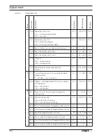
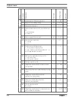
Страница 112: ...00 1200 2 201 Transmitting capacity of laser diode of bobbin thread monitor 0 off 255 max luminosity B C 0 255 100 206 Program interruption break off of seam section at fixed speed ON with pedal 2 OFF with pedal 0 B C ON OFF OFF 3 307 Delay time till stop of needle cooling after machine stop B C 0 2000 50 311 Stitch counting stop ON with thread trimming OFF without thread trimming B C ON OFF ON 32...

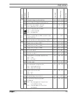
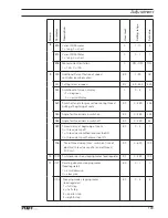
Страница 113: ...imit at stroke 2 3745 B C 300 5000 2900 588 Speed limit at stroke 3 3745 B C 300 5000 2000 589 Speed limit at stroke 4 3745 B C 300 5000 1100 6 606 Minimum speed B C 30 650 180 607 Maximum speed B C 300 3200 2500 608 Speed phase curve pedal characteristic ON linear OFF non linear B C ON OFF OFF 609 Cutting speed B C 60 300 180 615 End recognition with light barrier ON from bright to dark OFF from ...

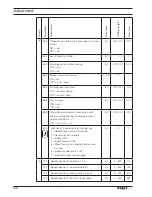
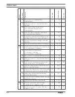
Страница 114: ...FF no B C ON OFF OFF 688 Thread tension release in connection with the presser foot during intermediate stop if parameter 636 is at 1 ON yes OFF no B C ON OFF ON 695 Function of needle position change key 1 Needle raised without trimming 2 Needle position change 3 Single stitch 4 Single reverse stitch 5 Move forward to a needle position step by step 6 programmable tack on off 7 proceed to next sew...

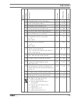
Страница 115: ...effected ON sewing motor stop and signal lamp on OFF signal lamp on B C ON OFF ON 729 Start delay after presser foot lowered B C 10 2550 140 730 Lift delay for presser foot after seam end B C 0 2000 100 750 Increased standstill brake in case of docu seam error B C 0 100 70 760 Remaining no of stitches after response of bobbin thread monitor during monitoring fixed value x 10 A B C 1 250 20 770 Lif...

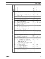
Страница 116: ...osition 2 Max brake on positioning speed and ooow ait till target position is reached C 1 2 2 815 Rotor position definition after mains ON 1 with rotary field 2 with current impulse C 1 2 1 880 Starting current max A C 1 20 10 881 Proportional amplification of speed control of sewing motor C 10 1000 250 884 Integral amplification of speed control of sewing motor B C 3 24 18 885 Proportional amplif...

Страница 117: ...g at beginning of seam B C 0 359 255 985 Angle for thread clamp switch on B C 0 359 224 986 Angle for thread clamp switch off B C 0 359 54 989 Thread clamp at beginning of seam 0 thread clamp off 1 thread clamp without presser foot lift 2 thread clamp with presser foot lift B C 0 2 1 996 Timer thread clamp max switch on time of electrical thread clamp after end of thread 100 ms B C 0 600 100 10 10...

Страница 118: ...B C 0 1 0 1202 Rotation direction thread tension 1 full step 2 half step 3 quarter step 4 eighth step B C 0 4 2 1203 Max current in stepping motor thread tension B C 1 100 100 1204 Reducing current in stepping motor thread tension B C 0 100 30 1205 Start stop time stepping motor thread tension time for one step at start stop speed B C 4000 300 1206 Roof time stepping motor thread tension time for ...

Страница 119: ...th appropriate authorization ON OFF OFF 2019 Docu seam ON Block sewing functions of keypad in ooodocumented seam sector OFF Functions always permitted B C ON OFF ON 2020 Docu seam P share of thread tension control A B C 0 10 1 2021 Thread tension while cutting cN A B C 0 500 50 2022 Stitch length of tie stitches A B C 10 30 15 2023 Selection mode for soft limit for docu seam 1 Docu seam fields onc...

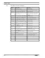
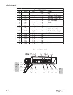
Страница 120: ...ror 63 Overload of 24V net adapter Check connected consumer Error 64 Supply OFF signal at power on Replace control Error 65 Error at power electronics at pow er up Replace control Error 66 Power electronics diagnostic re turned error Replace control Error 68 Overload on main drive Replace control Error 70 Motor blocked Check machine for sluggishness or replace motor Error 71 Incremental encoder of...

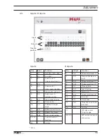
Страница 121: ...n lower thread 18 E52 Bobbin top thread 19 E53 Error straight edge 25 31 Control panel on machine 32 Hotkey Key Output Function 1 A6 Stroke adjustment 0 2 A11 Stop motion device reset 5 A12 Stroke adjustment 1 6 A13 Stroke adjustment 2 7 A3 Thread clamp 9 A15 Foot cleaning 10 A1 Motor run 11 A14 Stroke adjustment 3 13 A5 E winder 14 A4 Clamp foot 15 A8 Thread tension to be released 16 A9 Cutting 1...

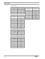
Страница 122: ... 4 ADTC 5 5V 6 Y EXT SM 7 15V 8 EXT SM 9 GND X3 SubD 9polar Speed control unit 5 5V 8 IN 9 GND X4 SubD 9polar Control panel 1 24V 2 RXD in 3 TXD out 4 5V 5 GND 7 RTS out 8 CTS in 9 NC X6 Modular jack 9polar Light barrier Stop motion device 1 NC 2 5V 3 GND 4 UFW Sensor 5 LS 6 24V 15V 7 UFW Laser 8 NC 4 11 Pin assignment ...

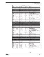
Страница 123: ...n10 1_1 E3 Switch slide stitch platen 15 16 17 18 Inputs 24V 19 Gnd OTE Gnd 20 Out1 10_0 A6 Stroke adjustment 0 21 Out2 10_1 A11 Stop motion device reset 22 A19 Counting impulse SyMa f stop motion device 23 I2C SCA OTE SCL 24 Out5 10_4 A12 Stroke adjustment 1 25 Out6 10_5 A13 Stroke adjustment 2 26 27 Out7 10_6 A3 Thread clamp pneum 28 Out8 10_7 A7 29 Out9 11_0 A15 Foot cleaning pneum 30 Out10 11_...

Страница 124: ...utputs OC 0 35A 12 Out17 12_0 A51 LED docu seam in straight edge 5 Out18 12_1 A52 13 Out19 12_2 A53 6 Out20 12_3 A54 14 Out21 12_4 A55 7 Out22 12_5 A56 8 Out23 12_6 A57 Control panel on machine 14_4 Out37 14_2 Out35 13_6 Out31 13_4 Out29 13_2 Out27 13_0 Out25 Port Service 14_7 Out40 Port Service 14_6 Out39 Port Service 3_7 In32 Port Service 14_5 Out38 3_6 In31 14_3 Out36 3_5 In30 13_7 Out32 3_3 In...

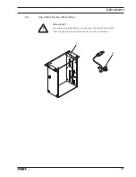
Страница 125: ...Adjustment 117 Attension To avoid wrong monitoring it is necessary to calibrate the system after changing the thread force sensor 2 or the control box 1 4 12 Importend Sevice information 2 1 ...

Страница 126: ......

Страница 127: ...Register 05 ...

Страница 128: ......

Страница 129: ...Kalibrieranleitung engl 06 12 CALIBRATION INSTRUCTIONS 3741 3745 ...

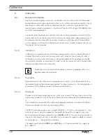
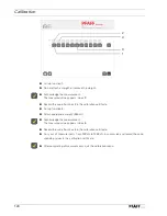
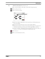
Страница 130: ...he permitted tolerance an adjustment is made so that the values are within the permitted tolerance and the calibration is repeated Calibration can be carried out by anybody In contrast to gauging there is no legal background for calibration 5 01 02 Traceability Traceability means that when measuring equipment is tested it must be possible to trace the documentation of the detailed readings back to...

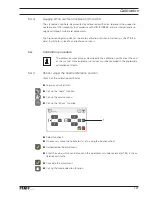
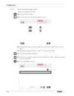
Страница 131: ... The calibration takes place as described in the calibration certificate at the end of this manual All calculated or set values must be recorded in the appropriate calibration certificate 5 02 01 Check adjust the needle reference position Item 1 of the calibration certificate Log in as administrator Call up the tools function Call up the service menu Call up the drives function Select function 1 I...

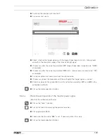
Страница 132: ...meter values By tapping the appropriate arrow symbol No select parameter 607 for the maximum speed By tapping the appropriate arrow symbol Val enter the value 500 Call up the mode selection function Call up the seam program selection function and select the manual program by tapping on the list of programs Call up the production function Industrial 1 Industrial ...

Страница 133: ...ccordingly Carry out another test seam and check the altered value If necessary repeat the procedure until the setting for the trigger signals is correct Enter the values for the speed 500 min 1 and for the parameters 2011 and 2013 in the calibration certificate Call up the mode selection function 5 02 03 Check the zero position of the monitor power signal Item 3 of the calibration certificate Cal...

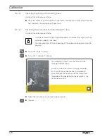
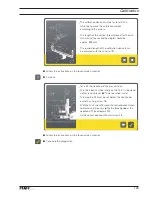
Страница 134: ...ollow the instructions on the touch screen monitor Scroll on 5 02 04 Checking the setting of the sewing head Item 4 of the calibration certificate Check the mechanical setting of the sewing head in accordance with the Adjustment Ma nual and adjust the sewing head if necessary _The calibration thread 1 must be fastend at the thread guide lose loop _Guide the calibration thread 1 through the guides ...

Страница 135: ...d the second bearing 8 should be approx 250 mm _The rquired length of the calibration device 4 can be adjusted with the wing nut 9 _Take off the needle and the presser foot _Turn the balance wheel and pos the M C in top dead center take up lever 66 balance wheel scale _Turn bearing 12 must be set below the needle bar eyelet by using screw 13 _With the knurl screw 15 move the red calibration thread...

Страница 136: ...tificate Call up function 3 Attach appropriate weight 500 cN Acknowledge the measurement The measured value appears in box 4 Record the value from box 4 in the calibration certificate Carry out all measurements from 100 cN to 1000 cN in succession and record the corre sponding values in the calibration certificate After completing all measurements quit the calibration menu Industrial 1 2 3 4 ...

Страница 137: ...ulum move ments have stopped Record the measured value shown in box 1 in the calibration certificate Repeat the measurements four more times and record each value in the calibration certi ficate The measured value must always be within the range of 500 cN 30 cN If there are deviations the characteristic thread strength curve must be re recorded in ac cordance with Chapter 5 02 05 Characteristic th...

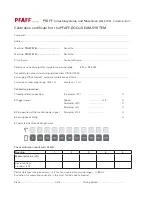
Страница 138: ...ation certificate End value of measuring range 1500 cN Accuracy 2 Calibration procedure 1 Needle reference position Parameter 700 O 2 Trigger signals Speed min 1 O Parameter 2010 O Parameter 2011 O 3 Zero position of the monitor power signal Parameter 2013 O 4 Sewing head setting O 5 Characteristic thread strength curve Check calibration result with 500cN Reading 1 2 3 4 5 Measured value cN Deviat...

Страница 139: ...Register 06 ...

Страница 140: ......

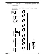
Страница 141: ...alves are in the machine s basic position Main switch ON compressed air ON Y3 Y6 Y12 Y14 Y13 Y4 Y9 Y15 3 6 12 13 14 15 9 4 Y8 8 Thread clamp Stroke adjustment Hook jet Trimming Automatic presser foot lift 91 510 083 95 Version 23 11 09 Pneumatics switch diagram Tread tension only 3745 Version PLUS ...

Страница 142: ...130 6 02 Block diagram PFAFF 3741 3745 with control unit P374 ED P374 ED PC Block diagram Version 23 11 09 only 3745 Version PREMIUM Version PLUS ...

Страница 143: ...guide with distance control SS Slide switch KS man Knee switch manual seam KS HV Knee switch stroke adjustment US Reverse fuse MSZ HV Stroke adjustment PF Presser foot FK Thread clamp SN Thread trimmer ML Motor running signal free GR Clean hook LS Light barrier FSL Release thread tension PC Docu seam PC TFT Monitor with touch screen EP Label printer HS Barcode hand held scanner ID BS LA Barcode sc...

Страница 144: ... B41 Oil sensor I2C Bus H1 Sewing lamp M1 Sewing motor M2 Stepping motor stitch length M11 Motor electrical bobbin winder M14 Stepping motor thread tension Q1 Main switch S1 1 Pedal speed control unit S1 S8 Key 1 Key 8 S22 Key electrical bobbin winder S24 Seam section optional S26 Key switchover fuse S27 Stroke adjustment option S51 Cop switch needle thread S52 Cop switch bobbin thread X0 RS 232 i...

Страница 145: ...S24 Seam section optional XS27 S27 Knee switch stroke adjustment XS50 Cop switch S51 and S52 XS51 Cop switch S51 XS52 Cop switch S52 XL10 Edge guide XY3 909 Y 3Thread clamp XY4 910 Y 4 Presser foot lift XY6 918 Y 6 Stroke adjustment 1 XY8 Y8Thread tension release XY9 900 Y 9Thread trimmer XY12 918 Y 12 Stroke adjustment 2 XY13 918 Y 13 Stroke adjustment 3 XY14 918 Y 14 Stroke adjustment 4 XY15 926...

Страница 146: ...hread cop X0 RS 232 controller interface P374 ED L X98 Plug from PCI Seriel RS 232 carde X99 RS 232 Adapter X98 X0 X100 Mains plug PC X101 USB plug PC A101 touchscreen monitor X102 USB plug PC B102 Barcode hand held scanner X103 USB plug PC free X104 USB plug PC XUSB7 Barcode label printer X105 USB plug PC free X106 USB plug PC free X107 USB plugPC free X108 USB plug PC free X109 USB plug PC A101 ...

Страница 147: ...135 91 191 528 95 Part 1 Version 12 01 12 Circut diagrams ...

Страница 148: ...136 Circut diagrams Version 12 01 12 91 191 528 95 Part 2 ...

Страница 149: ...137 91 191 528 95 Part 3 Version 12 01 12 Circut diagrams ...

Страница 150: ...138 Circut diagrams Version 12 01 12 91 191 528 95 Part 4 ...

Страница 151: ...139 91 191 528 95 Part 5 Version 12 01 12 Circut diagrams ...

Страница 152: ...140 Circut diagrams Version 12 01 12 91 191 528 95 Part 6 ...

Страница 153: ...141 91 191 528 95 Part 7 Version 12 01 12 Circut diagrams ...

Страница 154: ...142 Circut diagrams Version 05 01 12 91 191 536 95 ...

Страница 155: ...143 91 191 536 95 Version 12 01 12 Circut diagrams ...

Страница 156: ...autern Phone 49 6301 3205 0 Fax 49 6301 3205 1386 E mail info pfaff industrial com Printed in Germany PFAFF Industriesysteme und Maschinen AG 2009 PFAFF is the exclusive trademark of VSM Group AB PFAFF Industriesysteme und Maschinen AG is an authorized licensee of the PFAFF trademark ...

Отзывы: