background image

G.M. PFAFF
Aktiengesellschaft

Postfach 3020
D-67653 Kaiserslautern

Königstr. 154
D-67655 Kaiserslautern

Telefon: (0631) 200-0
Telefax: (0631) 172 02
Telex:  45753 PFAFF D

Gedruckt in der BRD
Printed in Germany
Imprimé en R.F.A.
Impreso en la R.F.A.
Stampato in R.F.G.

ïô

Ð

e  aôa

Ç

ï ÖÑÃ

Содержание 3822-1/22

Страница 1: ...manual The following other manuals are required Service manual for thread trimmer 900 51 of the 480 Series Motor control instructions 1 22 Quick digital P 40 K2 1 24 Quick digital Q 40 SE Betriebsanleitung engl 03 94 296 12 17355 ...

Страница 2: ...ropriately trained persons Repairs conversion and special maintenance work must only be carried out by technicians or persons with appropriate training For service or repair work on pneumatic systems the machine must be isolated from the compressed air supply system Exceptions to this are only adjustments and function checks made by appropriately trained technicians Work on the electrical equipmen...

Страница 3: ...eutral position of bottom feed dog 18 21 Stitch length limitation 18 22 Bottom feed actuating lever 18 23 Bottom feed dog stroke 20 24 Bottom feed lifting motion 20 25 Bottom feed dog height 22 26 Spacing between presser foot and needle plate 22 27 Adjusting the floating foot 24 1 on 3822 1 24 24 1 1 Height adjustment 24 1 2 Distance screw 24 2 on 3822 1 22 24 28 Top feed driving link 26 29 Top fe...

Страница 4: ...etween rear top knife and hook knife 56 8 4 Setting the cutting depth of the rear top knife in relation to the hook knife 58 9 Settng the cutting depth of the front top knife 58 10 Setting the trimming margin 58 11 Basic adjustments on the top knife mounting 60 11 1 Cutting angle of the rear top knife 60 12 Sensor controlled monitoring of the hook knife 62 12 1 Function 62 12 2 Sensor adjustment 6...

Страница 5: ... s p m Maximum stitch length for 1 22 5 mm for 1 24 6 5x3 5 mm Needle system 134 KK Needle size 80 Trimming margin 5 0 mm on PFAFF 3822 1 22 6 5 x 3 5 mm on PFAFF 3822 1 24 Fabric clearance 7 mm Sewing motor for 1 22 Quick digital QD 552 P40 K2 for 1 24 Quick digital QE 5542 Q40 SE Power input 1 2 kW Connection voltage E 230 Volt 50 60 Hz Working pressure 6 bar Air consumption 40 standard litres W...

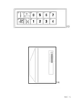
Страница 6: ...el see manufacturer s literature Twelve key panel 2 Controls and indicators General view onlywith3822 1 24 Knee switch for feathered edge trimmer for enabling and disabling Hook knife Blow impulse for ply separation Mains switch for switching on and off the entire sewing unit Knee switch for fullness By operating the knee switch it is possible to switch between the last gather amount that was inpu...

Страница 7: ...ktack switch off the machine sews a backtack according to the setting on the motor control panel see motor manufacturer s documentation at the beginning and at the end of the seam The backtack can be avoided by briefly touching the push button before actuating the treadle forwards or backwards respectively If no backtack is enabled it is nevertheless possible to recall the next backtack with this ...

Страница 8: ... hose internal dia of 6 mm to coupling Fig 1 Minimum supply pressure 7 bar Working pressure 6 bar Pressure adjustment regulating knob 2 5 2 Electrical 1 Permissible operating power is indicated on spec plate Fig 2 Note The operating voltage indicated on the specification plate refers to the control It is not necessarily applicable to the entire system 2 Connection must only be made if mains and op...

Страница 9: ...PFAFF 9 1 1 2 3 WARTEIN CDR 1 Kap03 2N 2 3 4 ...

Страница 10: ...hours a day Only use oil with a mean viscosity of 10 0 mm s at 40 C and a density of 0 847 g cmn at 15 C We recommend Pfaff sewing machine oil parts no 280 1 120 105 4 Lift sewing head back into position with both hands Risk of crushing between sewing head and table top 8 2 Rotating direction Requirement The balance wheel must rotate as shown by the arrow Fig 3 1 Switch on machine 2 Raise presser ...

Страница 11: ...PFAFF 11 1 KAP10 04 2 3 1 2 ÖL N ...

Страница 12: ...wards Winder is engaged 3 Thread up as shown in Fig 2 and wind thread a few turns around bobbin 4 Bobbin is filled during sewing 5 To regulate the amount of thread pin 2 screw 3 Note If bobbin is wound unevenly position thread guide 4 according nut 5 and regulate winding tension chapter 11 1 1 Regulating the winding thread tension Knurled washer 6 Fig 2 increase decrease ...

Страница 13: ...PFAFF 13 KAP07 1N KAP07 2N 2 1 1 1 2 3 5 6 4 ...

Страница 14: ...is pulled Fig 2 2 Hold bobbin pull thread through slot 2 and under tension spring 3 1 4 Regulating the bobbin thread tension Screw 4 increase decrease 15 Inserting the bobbin case 1 Oopen latch 1 Fig 1 2 Insert bobbin case in hook and release latch 1 must audibly snap in 3 Press bobbin lightly case to make sure it has snapped in properly 16 Threading the needle thread Switch off machine 17 Adjusti...

Страница 15: ...PFAFF 15 1 2 KAP13 02 2 4 3 KAP12 03 3 5 1 KAP08 04 ...

Страница 16: ... a little until pin enters the hole in the crank behind the bearing plate and blocks the machine 1 9 Needle to needle hole Requirement A perfectly straight needle must enter exactly in the centre of needle hole Fig 2 for needle system see Specifications 1 Loosen screws 2 3 and 4 Fig 3 2 Adjust needle bar frame 5 accordingly 3 Firmly tighten screw 2 4 Using screw 2 pull the guide pin behind it agai...

Страница 17: ...PFAFF 17 02 01 2 4 3 1 3 2 5 02 02 1 01 01 5 mm ...

Страница 18: ... out screw 6 Fig 4 accessible through fitting hole and insert screw at different setting 2 Set maximum stitch length of 3 mm lever 1 3 Place limitation stop 7 from top onto adjusting lever 1 and tighten it screw 6 22 Bottom feed actuating lever Requirement When the longest stitch length is set reverse feed lever 8 Fig 5 must have a slight play 0 3 to 0 5 mm when operated 1 Set longest stitch lengt...

Страница 19: ...PFAFF 19 1 KAP06 2N 5 8 2 3 03 01 1 45 45 45 45 45 2 2 03 2A 4 5 26 01 4 3 9 10 11 6 1 7 17 2N ...

Страница 20: ...t make any driving motion when the reverse feed lever is pressed Adjust eccentric 2 screws 3 24 Bottom feed lifting motion Requirement When the stitch length is set at 0 and the needle bar is set 0 6 mm past top dead centre adjustment hole 1 Fig 1 the bottom feed dog must be at the top of its stroke the cutout in eccentric 4 Fig 3 is facing vertically downwards Adjust eccentric 4 screws 5 ...

Страница 21: ...PFAFF 21 1 1 1 1 1 KAP05 00 1 2 4 KAP08 04 4 5 2x 4 3 KAP08 04 3 2x 2 17 2N ...

Страница 22: ...he feed slots and touch the adjustment gauge throughout its length Fig 2 Height adjustment rear screw 1 Fig 3 front eccentric sleeve 2 screw 3 26 Spacing between presser foot and needle plate Requirement Spacing with lifted hand lever 7 mm 1 Insert gauge fig 5 between presser foot and needle plate hand lever is lifted 2 Bring lifting piece 4 fig 6 in contact with presser bar lifting lever 5 screw ...

Страница 23: ...PFAFF 23 1 1 1 1 1 KAP05 00 1 2 3822 1 24 7mm 5 Adjustment gauge 61 111642 19 KAP29 05 4 6 4 5 KAP07 02 2 3 3 KAP08 04 1 ...

Страница 24: ...en gauge foot is resting on the needle plate 6 Unscrew gauge foot and screw on floating foot 27 1 2 Distance screw Requirement Screw 3 fig 3 must be turned in to such an amount that the bottom part of the floating foot see arrow touches the head of the screw only when the presser foot is lifted by more than the sum of the feed dog height and the workpiece thickness approx 0 5 mm Adjustment Screw 3...

Страница 25: ...PFAFF 25 KAP29 05 2 1 2 Lehrenfuß Best Nr 61 111639 20 1 3 3 4 0 5 mm 6 5 4 KAP30 05 ...

Страница 26: ...ovement 1 Set feed regulator lever 8 Fig 3 at 0 2 Set lever 9 Fig 3 parallel with lever 10 screw 11 3 Place adjusting link 7 onto pins 12 Fig 2 4 Set crank 13 screw 14 so that feeding foot does not make any feeding motion Fig 4 5 Adjust lever 15 Fig 1 screw 16 Fig 5 so that top feed foot does not make any feeding motion whwn connecting rod 17 nut 18 Fig 1 is moved up and down in the elongated hole...

Страница 27: ...PFAFF 27 6 4 1 11 02 4 10 02 1 3 1 4 KAP31 01 3 KAP06 2N 5 3 2 1 21 8 1 5 1 8 1 7 19 22 20 1 6 5 2 7 11 9 1 0 1 2 10 01 ...

Страница 28: ...ment The greatest clearance between top feed foot and needle plate when the stitch length is at 0 and the presser foot is resting on the needle plate Fig 4 on 706 82 the top feed foot is behind the needle is 1 3 mm 1 Set stitch length at 0 and lower presser foot onto needle plate 2 Increase presser foot pressure knurled screw 4 Fig 5 3 Basic setting of pin 5 eccentric side facing needle bar screw ...

Страница 29: ...PFAFF 29 KAP33 02 2 1 11 02 2 3 KAP29 05 4 6 KAP31 01 5 12 02 1 0 9 8 7 5 6 4 3 2x 1 1 1 1 1 KAP05 00 1 ...

Страница 30: ...1 screw 2 33 Top feed foot position Requirement When the bottom feed dog is at the top of its stroke the top feed foot must be parallel with the bottom feed dog Adjust eccentric pin 3 Fig 2 screw 4 34 Top feed synchronization Requirement At stitch length 3 both top and bottom feed motions must be the same length 1 Compensate by shifting pin 5 Fig 3 in elongated hole nut 6 2 Adjustment according to...

Страница 31: ...PFAFF 31 KAP13 01 1 2 1 2 3 4 KAP29 05 3 6 5 ...

Страница 32: ... its basic position screw 2 see chapter 20 36 Eccentric hook shaft bearing Requirement Clearance between hook point and centre of needle clearance cut must be 0 3 mm when the hook is loosened screw 3 and is up against the oil ring Fig 2 The backlash between the gear teeth must be only slight but still perceivable 1 Position hook shaft bearing 4 axially screw 5 2 Turn hook shaft bearing to adjust b...

Страница 33: ...PFAFF 33 2 1 KAP03 01 1 2 3 2x KAP17 01 0 3 mm 7 2x 4 5 3 6 KAP17 2N ...

Страница 34: ...rance between hook point and needle is 0 1 mm 1 Adjust needle bar screws 1 Fig 4 2 Adjust hook screws 2 Fig 3 38 Bobbin case opener height Requirement When bobbin case opener 3 is at its left reversal point Fig 5 the opening finger and the stop on hook base base 4 Fig 6 must be level with each other It must be possible to remove the bobbin case without hindrance Turn eccentric bearing 5 screw 6 Fi...

Страница 35: ...PFAFF 35 4 4 4 4 4 KAP05 00 KAP39 02 KAP39 03 0 8 mm 0 1 mm 1 2 3 2 KAP40 01 6 7 KAP17 2N 5 6 4 3 KAP02 01 1 4 5 KAP08 04 3 4 ...

Страница 36: ...tment of opening finger 1 Fig 2 fixing collar 6 Fig 3 must be moved against the opening finger and stop screw 7 set against stop pin 8 1 Axial and radial adjustment of bobbin case opening finger 1 at left reversal point of bobbin case opening shaft screw 9 2 Fixing collar 6 screw 7 40 Bobbin case opener movement Requirement When the needle bar is 1 8 mm past b d c adjustment hole 4 bobbin case ope...

Страница 37: ...PFAFF 37 KAP41 01 1 0 8 mm 2 KAP41 02 0 3 mm 4 5 2 1 3 KAP41 03 3 8 4 KAP08 04 6 7 10 11 2x 3 9 4 4 4 4 4 KAP05 00 5 ...

Страница 38: ...nd may deviate slightly from this basic setting 1 Check spring stroke loosen clamp plate screws and and turn thread tension accordingly 2 Thread regulator 3 screws 5 43 Bobbin winder Requirement When the bobbin winder is engaged the winding spindle must be driven reliably When it is disengaged friction wheel 6 Fig 3 must not touch winder driving wheel 7 Axial adjustment of bobbin winder driving wh...

Страница 39: ...PFAFF 39 2 KAP01 X1 1 2 0 5 mm KAP45 01 1 5 7 mm 4 KAP48 02 1mm KAP47 01 8 3 1 0 9 7 6 5 3 4 ...

Страница 40: ...r presser foot shoe 2 Adjust on eccentric sleeve 3 screw 4 45 Pressure of vibrating and lifting presser Requirement The pressure of the vibrating and lifting pressers must be adapted to each other so that perfect feeding is ensured even at the highest sewing speed 1 Vibrating presser basic adjustment screw 5 Fig 2 flush with beginning of thread 2 Lifting presser basic adjustment screw 6 at a dista...

Страница 41: ...PFAFF 41 KAP32 01 2 6 5 KAP29 05 1 3 4 2 1 12 mm ...

Страница 42: ...ar crank 12 into arm shaft crank 10 and onto needle bar stud 13 2 Swing up take up lever link 7 insert bearing pin 6 Position take up lever in middle of housing slot set bearing pin 6 and rear bearing bush without play against take up lever link 7 and tighten screw 5 firmly 3 Set needle bar at bottom dead centre 4 Set eccentric side of eccentric pin 9 towards rear see arrow at 9 Observe correct di...

Страница 43: ...PFAFF 43 KAP52 01 3 KAP32 01 2 KAP52 02 5 8 1 0 1 7 1 1 1 2 1 3 3 9 6 2 4 1 3x ...

Страница 44: ...lever 6 against lever 3 and tighten screw 5 5 Take off link 2 6 Select correct motor setting on control panel 7 Fig 3 cf motor manufacturer s literature 7 Sew a sample seam 48 Stitch condensation system Requirement When cylinder 8 Fig 1 is extended the machine must sew at a shorter stitch length than the one set on the feed regulator 1 Switch on stitch condensation key LED on 2 Sew a sample seam 3...

Страница 45: ...PFAFF 45 6 4 KAP54 01 1 3 9 8 5 1 10 2x 7 BI 02N 2 KAP31 02 KAP10 01 2 3 ...

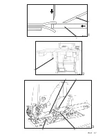
Страница 46: ... and the balance wheel is turned there must be no up or downward movement 1 Switch off trimming mechanism key LED off Fig 2 2 Turn eccentric pin 3 Fig 3 so that eyes of levers 4 and 5 are aligned with each other screw 6 3 Turn lever 7 until top knife is motionless when balance wheel is turned screw 8 49 3 Knife height Requirement When the knife is in its lowest position the front of the cutting ed...

Страница 47: ...PFAFF 47 1 5 05 00 4 3 56 04 9 1 0 5 0 5mm 56 xx 56 01 1 2 3 4 5 7 8 6 2 ...

Страница 48: ... top knife at lowest position balance wheel 3 Place top knife with light pressure against counter knife screws 13 Fig 7 Requirement Top knife 9 Fig 8 must be at a slight diagonal to counter knife 14 shearing action 4 Set knife bracket 11 Fig 7 at a slight diagonal screw 15 49 6 Adjusting the stop eccentric Requirement When stop 16 Fig 9 is resting on eccentric 17 there must be a clearance of about...

Страница 49: ...PFAFF 49 56 5x 6 7 56 04 12 13 15 8 57 02 9 1 0 56 07 9 56 06 1 9 1 8 5 mm 1 6 1 7 14 11 21 20 ...

Страница 50: ...parations for adjusting the trimmer Remove Presser foot Complete top knife bracket 1 loosen screws 2 Fig 1 Cover of knife drive 50 3 Setting the longest knife stroke Set actuating lever 3 Fig 2 right at bottom of elongated hole in lever 4 nut 5 50 4 Setting the top reversal point of the knife Requirement When the eye of the descending needle is level with the needle plate the downwards movement of...

Страница 51: ...PFAFF 51 2 KAP56 01 3 6 5 4 KAP33 02 1 1 2 3 ...

Страница 52: ...p knife 9 rests lightly against bottom knife screws 2 4 Turn top knife bracket 11 Fig 5 to one side according to requirement screw 12 Check with clearance gauge 50 5 2 Cutting position of the front top knife Requirement The rear edge of front top knife 9 must be absolutely flush with the edge marked in Fig 7 see arrow Adjustment Position knife bracket 1 Fig 1 according to requirement screw 13 50 5...

Страница 53: ...PFAFF 53 KAP56 02 4 8 7 KAP33 02 5 1 2 9 10 11 12 1 3 7 1 0 9 max 0 1mm 6 10 9 ...

Страница 54: ... be set at the highest point of its stroke Adjustment eccentric screw 16 screw 17 50 8 Positioning the rear top knife and hook knife after changing top knives For adjustments required after a new top knife bracket is fitted please see chapter 57 11 50 8 1 Lateral position of the rear top knife to hook knife Requirement The rear edge of rear top knife 7 Fig 11 must be flush with hook knife 20 see a...

Страница 55: ...PFAFF 55 8 15 14 17 KAP56 01 9 16 20 1 1 7 8 12 KAP33 02 9 1 0 18 2 0 ...

Страница 56: ...t cutting angle corresponds with requirement screw 22 6 Re connect compressed air 57 8 3 Cutting pressure between rear top knife and hook knife Requirement The cutting pressure must only be as much as absolutely necessary After the cutting pressure is set the diagonal position of hook knife 20 in relation to rear top knife 7 cutting angle set in chapter 50 8 2 must not be less than 0 05 mm Adjustm...

Страница 57: ...PFAFF 57 KAP56 10 KAP56 11 2 0 2 1 14 KAP33 02 24 22 23 15 7 0 05 0 1mm Cutting angle exaggerated KAP56 09 ...

Страница 58: ...ig 19 50 9 Setting the cutting depth of the front top knife Requirement Front top knife 9 Fig 21 must make two thirds of its cutting stroke before rear top knife 7 begins to cut 1 Fit front top knife 9 Fig 20 screws 18 2 Switch on trimming mechanism key LED on Fig 17 3 Set top knives in highest position balance wheel 4 Engage hook knife 20 knee switch 4 Fig 18 5 Adjust knife height front top knife...

Страница 59: ...PFAFF 59 17 9 KAP33 02 18 2 3 of cutting edge 7 25 18 56 22 21 2 0 9 1 9 18 KAP56 01 4 1 6 1 7 BI 02N ...

Страница 60: ...a diagonal of 0 05 to 0 1 mm in relation to hook knife 20 cutting angle Note Adjustment is made on three allen screws allen screw 26 is only accessible when rear top knife 7 has been removed 1 Remove top knife 7 2 Unscrew screws 26 and 27 just enough that they protrude by about 0 2 mm on the side of the top knife on which rear top knife 7 is afterwards fitted 3 Cement in screws 26 and 27 4 Screw o...

Страница 61: ...PFAFF 61 21 7 26 8 27 28 ...

Страница 62: ...or adjustment Requirement The sewing and cutting procedure must not start if working with feathered edge trimmer until hook knife 20 is in cutting position 1 Preliminary work Carry out optimum adjustment of hook knife 20 according to section 50 2 Attach feeler gauge 0 1 mm between stop bracket 32 and pin 31 3 Press key hook knife 20 positions in cutting position 4 Loosen screws 34 slightly 5 Move ...

Страница 63: ...PFAFF 63 23 3 5 33 35 3 4 20 22 29 30 31 3 2 3 6 3 6 Sensor1 ...

Страница 64: ...4 in starting position by pressing Either key or key or knee button 37 fig 26 2 Find the cause for the disturbance Possible causes dirt between stop bracket 32 and pin 31 lint is preventing hook knife 20 from reaching the cutting position dirt between slide 38 fig 24 and guide 39 slide is binding 3 Remove disturbance ...

Страница 65: ...PFAFF 65 2 6 37 2 5 2 4 38 39 20 32 31 ...

Страница 66: ...Set airblast 2 according to requirement 2 Air pressure regulation on throttle valve 3 Fig 3 3 Check switch on airblast knee switch 4 Fig 29 52 Airblast for cutting waste only for 1 24 Requirement The cutting waste must be reliably extracted into the waste chute 1 Set airblast 5 according to requirement 2 Air pressure regulation on regulator 6 Note Airblast only works during sewing action ...

Страница 67: ...PFAFF 67 KAP57 01 2 1 1 6 5 KAP33 02 3 2 3 4 2 BI 02N ...

Страница 68: ...ollowing adjustments see arrow in fig 2 6 Turn the angle encoder 3 until pointer 1 is in the zero position 5th graduation from the bottom of the scale fig 3 7 Tighten up nut 4 in this position 8 Check see requirement Screw on the protective cover of the angle encoder Mount cover plate 53 1 2 Precise adjustment on pot 0 Requirement When key is activated LED on the machine should sew without ply shi...

Страница 69: ...PFAFF 69 4 1 2 3 3 4 2 1 918 15N 5th graduation on scale zero position ...

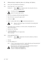
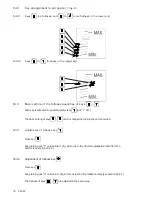
Страница 70: ...otentiometer key pot 1 etc The basic setting of keys can be changed by turning the pot concerned 53 3 1 Adjustment of fullness key Press key Keep turning pot 1 until pointer 1 fig 6 moves to the 4th scale graduation mark from the bottom see section 53 2 1 53 3 2 Adjustment of fullness key Press key Keep turning pot 2 until point 1 fig 6 moves to the 3rd graduation mark see section 53 2 1 The fulln...

Страница 71: ...PFAFF 71 5 7 6 1 918 15N ...

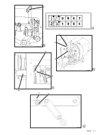
Страница 72: ... fig 10 must be mounted 1 Attach adjustment link 5 fig 8 2 Adjust stitch length 2 5 3 Switch on machine master switch Key is automatically activated LED on 4 Loosen screw 9 fig 11 5 Bring feed lever 6 fig 11 12 from below in contact with transmission crank 7 6 Tighten up screw 9 fig 11 Make sure that feed lever 6 is resting on the side of the bearing of the reverse feed crank 10 7 Check see requir...

Страница 73: ...PFAFF 73 10 01 1 2 6 6 6 5 7 918 15x 9 1 0 9 7 8 8 918 15N 1 0 1 1 ...

Страница 74: ...2 to 7 Example with stitch length 2 5 Test seam 1 Set desired stitch length 2 Switch on machine mains switch Key is automatically activated LED on 3 Join two workpieces of the same length approx 50 cm together 4 If the two workpieces are not joined together in a shift free condition carry out correction on potentiometer 0 fig 14 5 For setting the personally desired fullness assign the individually...

Страница 75: ...PFAFF 75 1 4 1 3 ...

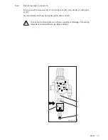
Страница 76: ...consideration of the above mentioned factors and the corresponding operating manual 2 In order to avoid disturbances we recommend the following cleaning intervals Entire unit at least once a week Hook area at least once a day 54 2 Air filter lubricator Check daily 1 Water trap bowl For max water level see arrow in Fig 1 Empty bowl 1 daily drain screw 2 2 Air filter Note Clean filter when working p...

Страница 77: ...y of 10 0 mm sec at 40 C and a density of 0 847 g cm at 15 C We recommend PFAFF sewing machine oil No 280 1 120 105 The oil used must have little or no effect on swelling or shrinkage of the sealing materials used under different operating conditions WARTEIN CDR 1 2 3 4 1 ...

Страница 78: ...ach 3020 D 67653 Kaiserslautern Königstr 154 D 67655 Kaiserslautern Telefon 0631 200 0 Telefax 0631 172 02 Telex 45753 PFAFF D Gedruckt in der BRD Printed in Germany Imprimé en R F A Impreso en la R F A Stampato in R F G ïôÐe aôaÇï ÖÑÃ ...

Отзывы: