


Adjustment
12 - 13
71-037
12
.05.10
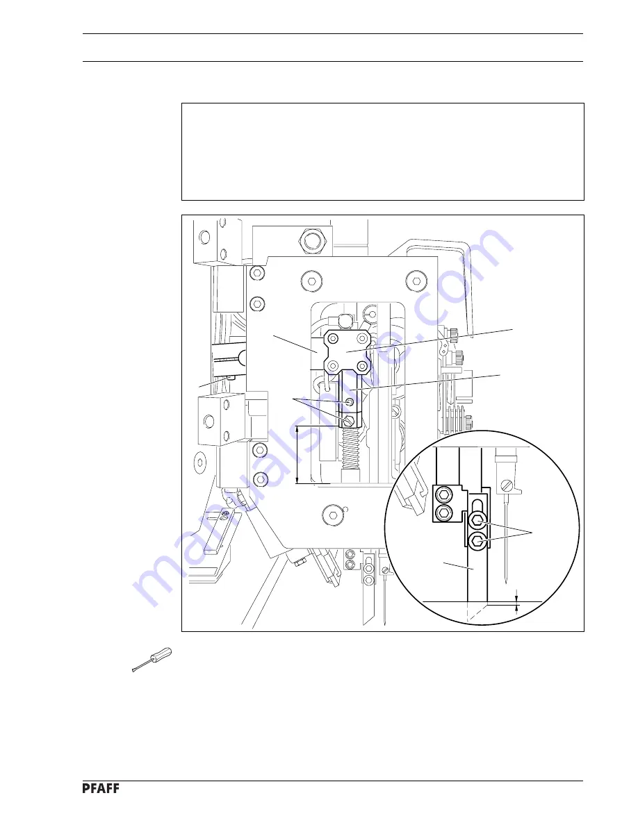
Height of the middle knife
Requirement
When the middle knife
5
is at its b.d.c.
1. The bottom edge of the knife holding bar
1
should be
40 mm
above the edge of the cast-
iron machine head.
2. Cylinder
7
should slot into the corresponding groove of the knife holding bar
1
.
3. The top edge of middle knife
5
should be
0.5 mm
below the needle plate cutout.
●
Adjust knife holding bar
1
(screw
2
) in accordance with
requirement 1
.
●
Move cylinder bracket
3
(screw
4
) in accordance with
requirement 2
.
●
Adjust middle knife
5
(screws
6
) in accordance with
requirement 3
.
Fig. 12 - 11
1
7
4
3
40 mm
71-038
6
5
0,5 mm
2
Содержание 3582-2/01
Страница 18: ...7 2 Controls 7 02 Catch of the folding unit Fig 7 03 After lifting catch 1 the folding unit can be retracted 1...
Страница 89: ...Register 08 Contents Chapter Page 13 Pneumatics circuit diagramc 13 1 Circuit diagrams 13 8...
Страница 91: ...13 2 Version 01 01 2002 Pneumatics circuit diagram Part 1 Q0 2 Q0 3 Q0 4 Q0 5 Y1 Y2 Y3 Y4 2 2 2 3 3 4 4 4 1 1...
Страница 92: ...13 3 Pneumatics circuit diagram Part 2 Version 01 01 2002 6 6 7 7 8 8 Q0 6 Y5 Y6 Y7 Y8 Q0 7 Q1 0 Q1 1 5 5...
Страница 94: ...13 5 Pneumatics circuit diagram Part 4 Version 01 01 2002 20 50 A0 20 150 B0 a0 b0 13 13 Q2 4 Y13A...
Страница 96: ...13 7 Pneumatics circuit diagram Part 6 Version 01 01 2002 a0 A0 14 14 Q2 5 Y14 Q2 6 Option Y15...
Страница 98: ...13 9 Version 01 01 2002 Circuit diagrams...
Страница 99: ...13 10 General Plan Inputs Version 01 01 2002...
Страница 100: ...13 11 Version 01 01 2002 General Plan Inputs Outputs...
Страница 101: ...13 12 General Plan Clamp Drive Version 01 01 2002...
Страница 102: ...13 13 Version 01 01 2002 General Plan Quick Mini Stop...
Страница 103: ...Notes...