Pfaff 2571ME PREMIUM Скачать руководство пользователя страница 33


Adjustment


33

1

.05.25 

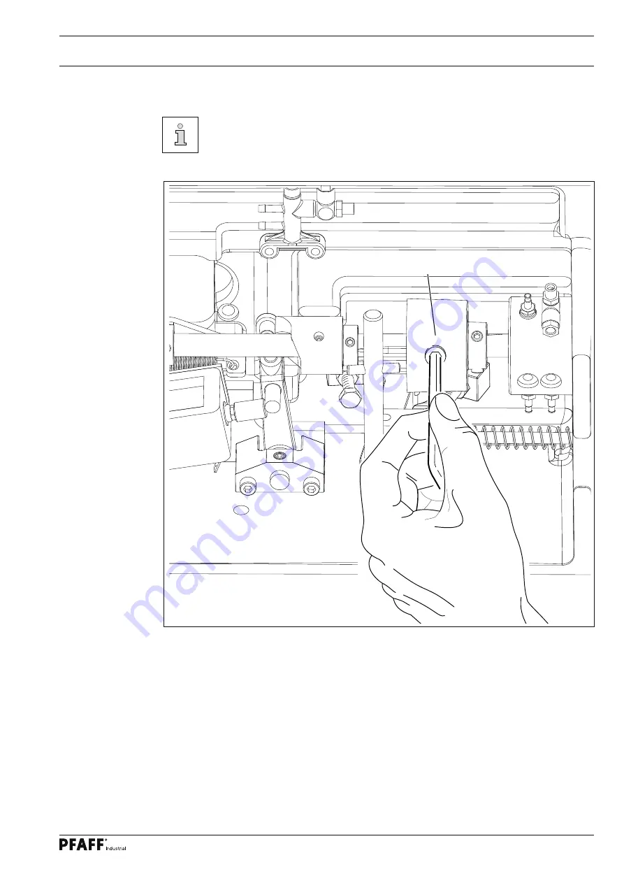
Re-engaging the slip-clutch

Clutch 

1

 is adjusted at the works.  In the case of a thread jamming, clutch 

1

 will 

disengage, in order to avoid damage to the hooks.

The following describes how to re-engage clutch 

1

.


Remedy jammed thread fault.


Hold clutch 

1

 fi rmly, as shown in Fig. 

1

 - 

19

, and turn the balance wheel until clutch 

1


re-engages.

Fig. 1 - 24

1

Содержание 2571ME PREMIUM

Страница 1: ...nual applies to machines from software version 0389 001 and serial number 2 766 760 onwards 296 12 19 129 002 Justieranleitung dtsch 01 11 SERVICE MANUAL 2571ME PLUS PREMIUM 2574 ME PLUS PREMIUM 2591M...

Страница 2: ...n of PFAFF Service Manuals whether in whole or in part is only permitted with our previous authorization and with written reference to the source PFAFF Industriesysteme und Maschinen AG Hans Geiger St...

Страница 3: ...eedle position crosswise to sewing direction on the PFAFF 2571 ME 18 1 05 11 Needle position crosswise to sewing direction on the PFAFF 2574 19 1 05 12 Needle position crosswise to sewing direction on...

Страница 4: ...04 Position of the thread catcher 44 1 07 05 Knife position and knife pressure 45 1 07 06 Bobbin thread retaining spring 46 1 07 07 Manual cutting test 47 1 07 08 Linkage rod only for the PFAFF 2574 M...

Страница 5: ...for machines which have to be completely adjusted If only specific individual work steps are carried out both the preceding and following chapters must be observed Screws nuts indicated in brackets ar...

Страница 6: ...01 Basic position of the balance wheel adjustment aid Requirement When the needle bar is positioned at t d c the marking 0 on the scale should be level with the top edge of the belt guard see arrow A...

Страница 7: ...2 Balance weight Requirement When the needle bar is positioned at b d c balance wheel position 180 the largest ec centricity of the balance weight 1 should be at the top Adjust balance weight 1 screw...

Страница 8: ...ear position of the needle according to the requirement Press the stitch control key sew a stitch and check the forward position of the needle ac cording to the requirement and where necessary make th...

Страница 9: ...the direction of sewing on the 2574 ME Requirement The needle must penetrate the middle of the needle hole as viewed in the direction of sewing 2 1 Move the needle bar frame 1 screws 2 3 and 4 in acco...

Страница 10: ...et at 5 when the needle is in its front and rear point of reversal screw 4 should be the same distance from the inside edge of its hole Set stitch length to 5 Select parameter 605 Turn the handwheel i...

Страница 11: ...re should be a gap between upper edge needle bar and upper edge needle pendulum of about 54 mm 2571 91 or 58 mm 2574 Fig 1 06 1 05 06 Preliminary adjustment of the needle height Without turning it re...

Страница 12: ...ed 2 0 mm after BDC balance wheel position 202 and the stitch length set at 0 8 1 the hook point must be at needle centre with a hook to needle clearance of 0 05 to 0 1 mm 2 the top of the needle eye...

Страница 13: ...dle guard 7 Adjust the needle height according to requirement 2 cf chapter 1 05 05 Preliminary Ad justment of Needle Height Move hook post according to requirement 1 and tighten screws 4 and 5 Move co...

Страница 14: ...sition 202 and the stitch length set at 0 8 1 the hook point must be at needle centre with a hook to needle clearance of 0 05 to 0 1 mm 2 the top of the needle eye must be 0 8 to 1 0 mm below the hook...

Страница 15: ...hapter 1 05 05 Pre adjusting the needle height Adjust both hook posts in accordance with requirement 1 and tighten screws 8 Tighten screws 1 and 6 Taking the play of the bevel gear into consideration...

Страница 16: ...the needle lightly Set stitch length at 0 8 Loosen screws 1 2 3 and 4 as well as screw 5 on both sides of the post Select parameter 605 Unscrew the needle plate Turn the handwheel four times in the d...

Страница 17: ...movement Move collar 7 up against bevel gear wheel 8 and tighten screws 1 Screws 5 remain loosened for further adjustments Adjust needle guard 6 screw 9 according to requirement 3 When changing a clam...

Страница 18: ...F 2571 ME Requirement As seen crosswise to the sewing direction the needle must penetrate in the centre of the needle hole Turn screws 1 screws 2 on both sides of the post according to the requirement...

Страница 19: ...wise to sewing direction on the PFAFF 2574 Requirement As seen crosswise to the sewing direction the needles must penetrate in the centre of the needle holes Shift bearing plate 1 screws 2 on both sid...

Страница 20: ...to sewing direction on the PFAFF 2591 ME Requirement As seen crosswise to the sewing direction the needle must penetrate in the centre of the needle hole Adjust feed wheel post 1 screws 2 3 and 4 acco...

Страница 21: ...has deflected the bobbin case to its furthest point the catch of the bobbin case should be 0 3 0 5 mm from the back edge of the needle plate recess Adjust bobbin case opener 1 screw 2 in accordance wi...

Страница 22: ...d to the feed wheel 4 it should have a vertical play of approx 0 3 mm Swing out the roller presser Loosen screws 1 and 2 Adjust drive wheel 3 according to requirement 1 taking care to see that the tee...

Страница 23: ...o pressure is applied to the feed wheel 4 it should have a vertical play of approx 0 3 mm Swing out the roller presser Loosen screws 1 and 2 two screws each Adjust drive wheel 3 according to requireme...

Страница 24: ...591 Requirement The feed wheel should protrude from the needle plate by tooth height approx 0 8 mm Swing out the roller presser Loosen screws 1 Adjust eccentric 3 fastening screw accessible through ho...

Страница 25: ...viewed in transverse direction of sewing Raise the roller presser 1 Place roller presser bracket 2 screws 3 flush to the bottom edge of presser bar 4 Always observe requirement 1 when carrying out th...

Страница 26: ...d be 8mm Set the roller presser down on the needle plate Decrease roller presser pressure Adjust lift piece 1 screws 2 according to the requirement 1 Push magnet bracket 3 screws 4 downwards as far as...

Страница 27: ...lever is pressed the roller presser should raise up 7mm 2 Before the roller presser raises up the knee lever should have a little bit of clearance Turn screw 1 nut 2 according to requirement 1 Turn sc...

Страница 28: ...05 20 Tension release Requirement With the roller presser raised the tension shims 3 should be about 0 5mm loosened from each other Raise roller presser and calibrate lever 1 screw 2 according to the...

Страница 29: ...sed around the hook the check thread spring 3 should rise slightly from the rest 1 Position rest 1 screw 2 in accordance with requirement 1 Turn sleeve 4 screw 2 to adjust the tension of thread check...

Страница 30: ...ding spindle must be driven reliably When it is disengaged friction wheel 3 should not be touching drive wheel 1 2 When it is switched off the bobbin winder must click securely into its end position k...

Страница 31: ...ent 31 Requirement 1 The material must be fed smoothly 2 No pressure marks should be visible on the material Turn adjustment screw 1 in accordance with the requirement 1 05 23 Sewing foot pressure Fig...

Страница 32: ...ok Check whether oil has been filled in and that there is no air in the oil lines Let the machine run for 2 3 min While the machine is running do not place hands in the needle or hook area Danger of i...

Страница 33: ...rks In the case of a thread jamming clutch 1 will disengage in order to avoid damage to the hooks The following describes how to re engage clutch 1 Remedy jammed thread fault Hold clutch 1 firmly as s...

Страница 34: ...d the adjusting wheel has been turned to its high est position 1 the knife holder 2 must be parallel to the post and 2 the top edge of the needle plate must be in the centre of the angular knife openi...

Страница 35: ...edge of the needle plate Switch off the machine and engage the edge trimmer Loosen screw 1 By turning sccentric 2 position the knife in the centre of its adjustment range Adjust knife holder 3 accordi...

Страница 36: ...t The knife stroke can be adjusted over a range from 1 0 to 3 5 mm allowing the best possi ble adaption to all materials used Turn eccentric 1 screws 2 so that the marking of the desired cutting strok...

Страница 37: ...n model 2591 ME Requirement The knife stroke can be adjusted over a range from 2 0 to 3 5 mm allowing the best pos sible adaption to all materials used Adjust crank 1 nut 2 in slotted lever 3 accordin...

Страница 38: ...is engaged and the needle is in the needle hole the stroke of knife 1 should be half in front of and half behind the needle when the motor shaft is turned by hand Switch off the machine and engage th...

Страница 39: ...ngaged and the needle is in the needle hole the stroke of knife 3 should be half in front of and half behind the needle when the motor shaft is turned by hand Switch off the machine and engage the edg...

Страница 40: ...insert but no whistling sound should occur during trimming PFAFF 2571 ME Adjust screw 1 screw 2 according to the requirements Carry out a cutting test and repeat adjustment if necessary PFAFF 2591 ME...

Страница 41: ...position 53 the control cam 1 should have just bought roller lever 4 to rest Create a distance of 50 mm between the highest point of control cam 1 screws 2 and collar 3 Move collar 4 into contact alo...

Страница 42: ...in the neutral position and the foremost position of the catcher the distance between the toothed segment 4 and the outer edge of the thread catcher holder 1 should be the same see arrow Adjust the t...

Страница 43: ...plate Requirement During its swivel movement thread catcher 1 should not pass the edge of the needle plate see arrow in magnification Move thread catcher 1 screws 2 two screws parallel to the thread c...

Страница 44: ...thread trimmer is in its neutral position the rear edge of thread catcher should be positioned approx 2 5 3 mm behind the edge of the knife Move thread catcher 1 screws 2 two screws in accordance wit...

Страница 45: ...nt 1 The knife 1 should be touching the needle plate 2 The knife pressure should be set as low as possible but the cutting operation should still be carried out reliably Move knife 1 screws 2 in accor...

Страница 46: ...accordance with requirement 1 Adjust the tension in accordance with requirement 2 by bending side 4 of the bobbin thread clamp spring 1 Control requirement 1 Switch off the machine and bring the take...

Страница 47: ...the needle thread and the bobbin thread must be perfectly cut and bobbin thread 3 retained Sew a few stitches Turn off the on off switch Carry out the cutting operation manually Check requirement 1 an...

Страница 48: ...8 Linkage rod only for the PFAFF 2574 ME Requirement When the thread trimmer is in its resting position the drive levers 1 must be parallel Adjust drive levers 1 screws 2 in accordance with the requir...

Страница 49: ...er 2500 ME PREMIUM only 0 99999 12000 106 Bobbin thread remaining counter 2500 ME PREMIUM only 0 999 100 107 Stitch length adjustment 2500 ME PLUS only 0 2 0 2 mm 0 108 Display main processer software...

Страница 50: ...ssignment 1 Half stitch 2 Needle up 3 Knee switch 1 3 1 205 Button F1 assignment 2500 ME only I Backtack suppression II Raise needle I II I 206 Open thread tension on stop and lift roller presser I OF...

Страница 51: ...7 30 2574 0 191 160 4 401 Time delay roller presser lift 0 01s 1 5s 0 02s 402 Delayed start after lowering roller presser 0 01s 1 5s 0 15s 403 Set roller presser lift must be increased for high foot p...

Страница 52: ...se button on machine head E1 603 Machine drive in home position see set up instructions 0 127 8 2 604 Run cold start 605 Stitch process with step motors by handwheel 606 Display speed control unit val...

Страница 53: ...0 1 0 720 Move positioner 1 2 2 800 801 Function group 100 access authorisation Operator level 0 1 0 802 Function group 200 access authorisation Technician level 0 1 1 803 Function group 300 access au...

Страница 54: ...tion 39 Establishing contact when turned on xxx sewing motor control unit error byte see Motor Errors E 3 Section E 4 End of section E 5 Pedal or half stitch button or single stitch button on machine...

Страница 55: ...sing for transmission reduction 173 Motor blocked in 1st stitch 175 Interior starting error 222 Dead man monitoring Error Description Error in SD memory card reader Error 27 1 No SD memory card insert...

Страница 56: ...n 3 25 on and the appropriate control software for the machine type must be installed on a PC The transfer of the data to the machine can be carried out with a null modem cable part no 91 291 998 91 o...

Страница 57: ...al in the file PFPHILFE TXT which can be called up from the PFP boot program by pressing the help but ton 1 11 02 Updating 2500 PREMIUM with SD card After downloading the PFP tool and the control soft...

Страница 58: ...not be switched off When the update has been completed switch off the machine and remove the SD card Switch on the machine A plausibility control is carried out and if necessary a cold start To updat...

Страница 59: ...ontrol unit S20 Knee switch S24 Starting inhibitor button S41 Hand operation front button S42 Single stitch button change needle position S43 Thread tension release FSL S44 Automatic presser foot lift...

Страница 60: ...60 Circuit diagrams...

Страница 61: ...61 Circuit diagrams...

Страница 62: ...62 Circuit diagrams...

Страница 63: ...63 Circuit diagrams...

Страница 64: ...o pfaff industrial com Hotlines Technical service 49 175 2243 101 Application consultance 49 175 2243 102 Spare parts hotline 49 175 2243 103 Printed in Germany PFAFF Industriesysteme und Maschinen AG...

Отзывы: