background image

Set-up

42


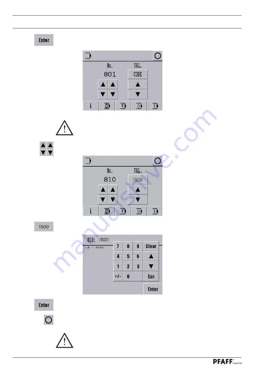
Adopt the code number entered.


Call up parameter ’

810

’.


Call up the code number input menu and enter the desired code number.


Adopt the new code number.


Conclude the input.

The code entered remains saved until the machine is switched off by the main 

switch. Provided that the machine is not turned off, all parameters can be ac-

cessed without re-entering the code number.

Remember the code!

Protected functions cannot be called up without the corresponding code! In 

this case, request support from the PFAFF service centre.

Содержание 1591

Страница 1: ...1591 1593 296 12 19 390 002 Instruction manual engl 04 18 This instruction manual applies to machines from the follow ing serial numbers onwards INSTRUCTION MANUAL ...

Страница 2: ... Geiger Str 12 IG Nord D 67661 Kaiserslautern This instruction manual applies to all models and subclasses listed in chapter 3 Technical Data The adjustment manual for the machine can be downloaded at no charge under www pfaff industrial de de service support downloads technical As an al ternative to the Internet download the adjustment manual can also be ordered as a hard copy under order no 296 ...

Страница 3: ...e customer s premises 14 5 03 Disposal of the packaging materials 14 5 04 Storage 14 6 Work Symbols 15 7 Operating Controls 16 7 01 Main switch 16 7 02 Keys on the machine head 16 7 03 Bobbin thread monitoring using stitch counting 17 7 04 Pedal 17 7 05 Hand lever to raise the roller presser 18 7 06 Swivelling out the roller presser 18 7 07 Knee switch 19 7 08 Knee lever 19 7 09 Edge trimmer 725 0...

Страница 4: ...engths 36 9 08 Entering start and end backtacks 37 9 09 Switching on setting the bobbin thread monitoring using stitch counting 39 9 10 Entering changing the code number 41 9 11 Setting the control panel 43 9 12 Inserting and removing the SD memory card 44 10 Sewing 45 10 01 Manual sewing 45 10 02 Sewing with fixed programs 47 10 03 Programmed sewing 49 10 03 01 Program interruption 51 10 04 Error...

Страница 5: ...iling the hook 74 12 04 Checking the oil level of the hook and front parts 74 12 05 Lubricating the bevel gears 75 12 06 Topping up the thread lubrication oil reservoir 75 12 07 Lubricating the roller presser drive gear mechanism only for a diameter of 25 mm and 35 mm 76 12 08 Cleaning the blower air filter 76 13 Table Top 77 13 01 Tilt base 77 13 02 Table top cutout 78 14 Wear and Tear Parts 79 ...

Страница 6: ...le adhering to all the relevant safety requirements The machine must always be disconnected from the power supply by pressing the main switch or pulling out the mains plug when sewing tools are replaced such as the needle presser foot needle plate and bobbin and when threading leaving the workstation or performing maintenance The daily maintenance work may only be carried out by suitably qualified...

Страница 7: ...tention for the owner operator This instruction manual is a part of the machine and must be made available to the oper ating personnel at all times The instruction manual must have been read before the ini tial start up The operating personnel and technical staff must be instructed about the machine s safe ty covers and about safe working methods The owner operator may only operate the machine in ...

Страница 8: ...uthorised persons are located in the machine s hazard zone Any changes occurring on the machine which impair its safety must be reported to the owner operator immediately 1 05 02 Technical staff Technical staff are persons with technical training in electricity electronics and mechanics They are responsible for lubricating servicing repairing and adjusting the machine The technical staff are oblig...

Страница 9: ...ed or be slung away Risk of injury from parts flying around Do not operate the machine without the take up lever guard 1 Risk of injury due to the motion of the take up lever Do not operate the machine without the belt guard 2 Risk of injury due to the rotating driving belt Do not operate the machine without the anti tipping device 3 Risk of injury from crushing between the sewing head and the tab...

Страница 10: ...peed seamer post is positioned to the right of the needle with forwards and backwards moving feed wheel and roller presser The machines are used to create double lockstitch seams in the leather and upholstery in dustries Any usage not approved by the manufacturer is deemed misuse The manufac turer shall assume no liability for damage caused by misuse Proper use also includes compliance with the op...

Страница 11: ...roller presser for a diameter of 25 mm and 35 mm 12 mm Passage width 245 mm Clearance height 115 mm Post height 180 mm Bed plate dimensions 518 x 177 Sewing head dimensions Length approx 562 mm Width approx 250 mm Height above table approx 505 mm Motor data see motor specification plate Noise data Noise measurement in accordance with DIN 45 635 48 A 1 ISO 11204 ISO 3744 ISO 4871 Model B Emissions ...

Страница 12: ... 12 mm Passage width 245 mm Clearance height 115 mm Post height 180 mm Bed plate dimensions 518 x 177 Sewing head dimensions Length approx 562 mm Width approx 250 mm Height above table approx 505 mm Motor data see motor specification plate Noise data Noise measurement in accordance with DIN 45 635 48 A 1 ISO 11204 ISO 3744 ISO 4871 Emissions sound pressure level in the workplace at n 2800 min 1 Lp...

Страница 13: ...arious plastics The electrical equipment consists of plastics and copper The machine must be disposed of in accordance with the locally valid environmental protection regulations with a specialised company being contracted if necessary Please ensure that parts coated with lubricants are disposed of separately in accordance with the locally valid environmental protection regulations ...

Страница 14: ...lease ensure that the machines are only transported in a vertical po sition 5 03 Disposal of the packaging materials The packaging materials of these machines consists of paper cardboard and VCI fleece It is up to the customer to dispose of the packaging properly 5 04 Storage The machine can be stored for up to 6 months when not in use It must then be protected from dirt and moisture For longer st...

Страница 15: ...rmed or important information in this instruction manual are emphasised by symbols The symbols used have the following meaning Note information Cleaning care Lubrication Maintenance repairs adjustment service work only to be carried out by technical staff ...

Страница 16: ...ned functions using parameters 203 and 204 See chapter 11 04 Parameter set tings The sewing lamp integrated onto the machine head is switched on and off with the key 3 Fig 7 02 7 Operating Controls 7 01 Main switch Fig 7 01 1 1 2 3 Before switching on the machine raise the take up lever as far as possible Turning the main switch 1 switches the machine on and off ...

Страница 17: ...the thread and changing the bob bin For presetting the stitch count please refer to chapter 9 09 Switching on setting the bobbin thread monitoring us ing stitch counting Fig 7 03 1 7 04 Pedal With the main switch turned on 0 Neutral position 1 Sewing 1 Raise roller presser 2 Trim thread Other pedal functions can be set through the programming see chapter 10 Sewing 0 2 1 Fig 7 04 1 ...

Страница 18: ...o raise the roller presser Turning the hand lever 1 raises the roll er presser 7 06 Swivelling out the roller presser The roller presser 1 can be swivelled out by gently pulling downwards when the roller presser is in the raised position Fig 7 06 1 1 ...

Страница 19: ...ssing the knee switch 1 It is possible to move to the next seam zones in programmed sewing by using the knee switch 1 The function of the knee switch 1 must be activated on the con trol panel see chapter 10 Sew ing Fig 7 07 1 7 08 Knee lever Pressing the knee lever 1 in the direc tion shown by the arrow raises the roll er presser Fig 7 08 1 ...

Страница 20: ...guide 2 moves to the operating position Switching off the edge guide Raise the edge guide 2 and allow it to engage the edge guide 2 is out of operation Raise the lever 4 the edge guide swivels away backwards Replacing knives The work described below may only be carried out by technical staff or people with appropriate training Switch off the machine Release the screw 5 and remove the knife 6 Inser...

Страница 21: ...e respective point on the monitor Pressing the respective function causes its immediate ac tuation or activation deactivation or another menu will appear e g for entering a value Acti vated functions are indicated by pictograms shown inversely Apart from the bobbin change function the pictograms and texts without border are only for display purposes and can not be called up by pressing them The SD...

Страница 22: ...ns must be provided at the erection site see chapter 3 Technical Data The erection site must also have a firm and level subsurface and adequate lighting The table top is lowered for packaging purposes The adjustment of the table height is described below 8 01 01 Setting the table height Fig 8 01 The stand must have all four feet firmly on the ground to make sure it is positioned se curely Loosen t...

Страница 23: ...e screwed to the sewing head base plate Insert the sewing machine into the table top Insert the sewing head support 2 into the table top hole Do not operate the machine without the support 2 Risk of damage due to the top heavy sewing head Machine can tip over backwards when moving it Fig 8 02 1 1 2 ...

Страница 24: ...m crushing be tween the sewing head and the table top 1 8 02 Mounting the flange motor 8 02 01 Mounting the flange motor on the bearing plate Fix the bearing plate 1 onto the motor 2 using the screws 3 as shown in fig 8 04 Remove the wedge from the motor shaft 4 Attach the angle bracket 5 with the screws 6 Mount the toothed belt wheel 7 onto the motor shaft 4 so that the screw 8 is positioned with...

Страница 25: ... 4 to fix the bear ing plate 1 of the motor 2 to the ma chine housing tighten the screws 3 and 4 slightly 1 4 3 2 8 02 03 Mounting the machine cover Use the screws 2 2x and the screws 4 3x to fasten the cover 1 to the housing Place the cover 3 on the cover 1 and fas ten with the screws 4 3x Fig 8 06 1 2 3 4 4 ...

Страница 26: ...llowing ground cables in order to discharge static electricity Securely attach the ground cable from the sewing head 1 to ground point A Securely attach the ground cable from the control point B to ground point B Securely attach the ground cable from the main switch 3 to ground point C Securely attach the ground cable from the stand 4 to ground point D Securely attach the ground cable from the mot...

Страница 27: ...ber see chapter 9 10 Entering changing the code number Turn the motor shaft by hand until the display shows the value 11 under POS Turn the handwheel in the direction of rotation until the needle point approaching from above is on the upper edge of the needle plate Fit the toothed belt 5 while making sure that both the motor shaft 4 Fig 8 08 and the machine are not twisted 11 ...

Страница 28: ...on Turn the handwheel in the direction of rotation until the needle point approaching from above is on the upper edge of the needle plate and check the value again 2 incre ments are permitted as a tolerance Conclude the entry 4 5 7 6 7 8 02 06 Mounting the flange motor belt guard Attach the belt guard 1 with the screws 2 and 3 Fig 8 09 1 2 3 ...

Страница 29: ...venting the machine starting up if the main switch is turned on Fig 8 10 1 2 8 02 08 Checking the start inhibitor function Switch on the machine at the main switch and let the sewing head rest on the sewing head support The STOP symbol must appear on the control panel If the symbol is not displayed check the safety switch setting Return the sewing head to its upright position The machine is ready ...

Страница 30: ...ange for technical staff to check whether the machine s motor may be operated at the existing mains voltage and whether it is connected properly Never operate the machine if there are any differences The machine must only be connected to a grounded socket Arrange for the home position of the machine drive to be verified by certified technicians before the initial start up Have these settings carri...

Страница 31: ...or all set up work by operat ing the main switch or by removing the mains plug 9 01 Inserting the needle Fig 9 01 2 1 Switch off the machine Risk of injury due to accidental machine start up Only use needles of the system intended for the machine see chapter 3 Tech nical Data Raise and fold out the roller presser 3 Move the needle bar to the top position Loosen the screw 1 and insert the needle 2 ...

Страница 32: ...ewing If the machine is only run for bobbin winding without sewing a bobbin case must be fitted in the hook Otherwise a jammed thread may damage the hook The tension of the thread on the bobbin 1 can be adjusted with the knurled thumb screw 4 The bobbin winder stops automatically when the bobbin 1 is sufficiently full Remove the filled bobbin 1 and cut the thread with the knife 5 The fill amount o...

Страница 33: ...se Move the lever 1 and close the post cover 9 03 Removing inserting the bobbin case 9 04 Inserting the bobbin case adjusting the bobbin thread tension Fig 9 03 1 2 Do not operate the machine with an open post cover Risk of injury due to moving parts Switch off the machine Risk of injury due to accidental machine start up Insert the bobbin as shown in Fig 9 05 When the thread is drawn off the bob ...

Страница 34: ...d tension Switch off the machine Risk of injury due to accidental machine start up Thread the needle thread as shown in Fig 9 05 Please ensure that the needle is thread ed from left to right Adjust the needle thread tension by turning the knurled thumb screw 1 Fig 9 05 1 ...

Страница 35: ... the desired program number or enter it via the keypad Confirm the selection and leave the selection menu The selection of the program number determines the type of sewing see chapter 10 Sewing Program number 0 Manual sewing Program numbers 1 and 2 Sewing with fixed programs Program numbers 3 to 49 Programmed sewing ...

Страница 36: ...changed directly in manual sewing and in the fixed programs 1 and 2 Switch the machine on Call up the stitch length input menu Change the feed motion for the roller presser and feed wheel individually or Change the feed motion for the roller presser and feed wheel at the same time Conclude the input ...

Страница 37: ...tch the machine on Call up the menu for inputting the start backtack Select the desired type of start backtack the selected active function is displayed in versely No start backtack Simple start backtack Double start backtack Enter the number of stitches for forward and reverse stitches Enter the backtack speed If necessary switch on the pedal controlled speed When the function is active inverse s...

Страница 38: ...ion Conclude the start backtack input Call up the menu for inputting the end backtack The values for the end backtack are entered in the same way as for entering the values for the start backtack The pedal controlled backtack speed and the placed stitch position cannot be called up at the seam end ...

Страница 39: ...witching on setting the bobbin thread monitoring using stitch counting Switch the machine on Call up input mode Call up parameter 104 Call up parameter 105 Switch on bobbin thread monitoring via stitch counting value 1 ...

Страница 40: ... the input The diode flashes on the keypad on the machine head on reaching the stitch count en tered The CHANGE BOBBIN message appears on the display after thread trimming see also chapter 11 05 Error messages and description Confirm the error correction after changing the bobbin ...

Страница 41: ...10 Entering changing the code number Switch the machine on Call up input mode Call up parameter 810 Call up the code number input menu Enter the code number using the numeric keypad code set at the factory is 1500 ...

Страница 42: ...nclude the input The code entered remains saved until the machine is switched off by the main switch Provided that the machine is not turned off all parameters can be ac cessed without re entering the code number Remember the code Protected functions cannot be called up without the corresponding code In this case request support from the PFAFF service centre ...

Страница 43: ...nput mode Call up the service menu Call up the control panel functions It is not possible to change the display contrast on the BDF P1 Switch the key tone off or on Conclude the input Never reduce the display contrast to such an extent that the display can no longer be read ...

Страница 44: ...er 1 Press gently on the corner of the SD memory card 2 the SD card will be ejected Close the cover 1 again Adjusting the slide 3 makes it possible to activate LOCK position or deactivate the write protection function on the SD memory card The write protection function must be deactivated to store edit or delete data on the SD memory card The SD card must be kept for future boot processes The SD c...

Страница 45: ...itch position when sewing thread tension and the needle and foot positions are displayed on the control panel in manual sewing and can be changed directly Fullness can be controlled via the stitch length input on the control panel or using the left pedal If the fullness is called up via the left pedal the current value of the fullness appears as a bar graph display below the stitch length indicato...

Страница 46: ...en pressed twice the next two bartacks are suppressed Needle position raised If this function is on the needle moves to the top position when sewing stops thread lever t d c Thread trimming When the function is activated thread trimming with the pedal function is possible Roller presser up When this function is activated the roller presser is raised after sewing stops Roller presser down after thr...

Страница 47: ...ocking placed stitch position when sewing needle and foot positions and the thread tension apply across the entire area and can be changed at any time Switch on the machine and select program number 1 or 2 see chapter 9 06 Select ing a program number Explanation of the displays and functions Program selection Opens the menu for inputting the program number see chapter 9 06 Selecting a program numb...

Страница 48: ... top position when sewing stops thread lever t d c Thread trimming When the function is activated thread trimming with the pedal function is possible Roller presser up When this function is activated the roller presser is raised after sewing stops Roller presser down after thread trimming When this function is activated the roller presser is not raised after thread trimming Sewing is performed usi...

Страница 49: ...respective seam zone number parameter feed motion of the top feed roller presser with fullness correction feed motion of the bottom feed feed wheel seam zone length are displayed for the current seam zone The feed motion of the top feed roller presser or the fullness correction can be changed directly Switch on the machine select the desired program number from 3 to 49 see chap ter 9 06 Selecting ...

Страница 50: ...resser down after thread trimming When this function is activated the roller presser is not raised after thread trimming Sewing is carried out using the pedal and knee switch functions see chapter 7 04 Ped al If the knee switch should be used to switch between the seam zones parame ter 201 must be set to ON The switch over between the seam zones can only be made using the knee switch with this par...

Страница 51: ... tension and perform the other functions as in manual sewing see chapter 10 01 Manual sewing Or call up manual sewing 10 04 Error messages If an error occurs the text ERROR appears on the display together with an error code An error message is generated by incorrect settings faulty elements or seam programs as well as overloading For an explanation of the error codes see chapter 11 05 Error codes ...

Страница 52: ...lue of the selected parameter see chapter 11 04 02 Example of a parameter input Software information Calls up information about the current machine software Create correct program Opens the menu for entering or changing seam programs see chapter 11 01 02 Seam program input via the Create correct program function Teach in Opens the menu for entering seam programs by stitching a sewing sample see ch...

Страница 53: ...e Create correct program and Teach in func tions and consist of the basic size the feed motion of the bottom feed feed wheel and the seam type Switch the machine on Select a program number from 3 49 see chapter 9 06 Selecting a program number Call up input mode Call up the Create correct seam program or Teach in function Select the desired program number or enter it via the keypad Make the basic s...

Страница 54: ... zones see chapter 11 01 02 Seam zone input via the Create correct program function or chapter 11 01 03 Seam program input via the Teach in function The input can also be concluded by calling up the sewing mode This function is used to conclude the seam program input and the machine switches to the pro grammed sewing mode Define the feed motion for the feed wheel as a basic stitch length ...

Страница 55: ...sting seam programs Switch the machine on Select a program number from 3 49 see chapter 9 06 Selecting a program number Call up input mode Call up the Create correct seam program function Select the desired program number or enter it via the keypad Make the basic settings and conclude the input with the Enter function see chapter 11 01 01 Basic seam program input setting Call up the comment input ...

Страница 56: ...rent seam program can be rolled through via the functions The current seam zone is displayed accordingly alongside all other current values Opens the menu for entering the seam start see chapter 9 08 Entering start and end backtacks Or insert the seam zone The current seam zone is copied and all subsequent seam zones are set backwards Or delete the current seam zone Define seam or programming end ...

Страница 57: ...9 see chapter 9 06 Selecting a program number Call up input mode Call up the Teach in function Select the desired program number or enter it via the keypad Conclude with the Enter function Call up the comment input menu Enter a comment via the keypad and numeric keypad Conclude the comment input The following displays and functions appear on the display before sewing Define the feed motion for the...

Страница 58: ...ngth de termines the fullness Enter the front backtack functions at seam start see chapter 9 08 Entering start and end backtacks The seam area is determined in stitches and shown on the display After sewing the following information and functions appear on the display Define seam or programming end End the input and change to programmed sewing ...

Страница 59: ... and be saved under program number 10 With the commend Seam 1 Switch the machine on Select program number 10 see chapter 9 06 Selecting a program number Call up input mode Call up the Create correct seam program function Select the desired program number or enter it via the keypad Conclude with the Enter function Call up the comment input menu Enter a comment via the keypad and numeric keypad Conc...

Страница 60: ...m zone In the second seam zone the number of stitches should be 25 stitches the roller presser should work with a feed motion stitch length of 2 6 mm Select the value 2 6 for the feed motion stitch length of the roller presser Switch over to enter the second seam left seam Enter the seam zones of the left seam in the same way as the above mentioned seam zones Activate the End program function Conc...

Страница 61: ... Selecting a program number Call up input mode Call up the Teach in function Select the desired program number or enter it via the keypad Conclude with the Enter function Call up the comment input menu Enter a comment via the keypad and numeric keypad Conclude the comment input The following displays and functions appear on the display before sewing Define the feed motion for the feed wheel This i...

Страница 62: ...the input of the seam program and change to programmed sewing Select the desired type of end backtack the selected active function is displayed in versely No end backtack Simple end backtack Double end backtack Thread trimming When the function is activated thread trimming with the pedal function is possible Roller presser up When this function is activated the roller presser is raised after sewin...

Страница 63: ...l take up to 20 s until the SD card is recognised as inserted Switch the machine on Call up input mode Call up program management SD card and machine memory are re read Description of the functions Input mode Calls up the basic screen of input mode Sewing mode Quit input mode and call up sewing mode Program selection At least one seam program is always marked after calling up the program managemen...

Страница 64: ...DAT the machine data can be copied or deleted on the SD card Format the SD card The SD card is formatted after pressing FORMAT A prompt for confirmation is displayed be fore the SD card is formatted The card is completely formatted if it cannot be read All programs and machine data in this directory are deleted if they can be read and the directory P1591 for the 1591 exists If the directory P1591 ...

Страница 65: ... which the individual parameters can be directly called by pressing the desired function All parameter groups or also individual ones can be protected by a code against unauthorised access Select parameter 100 User level 200 Mechanic level 300 Sewing motor positions 400 Times 500 Counter and speeds 700 Sewing motor 800 Access rights ...

Страница 66: ...ample set value 4 0 Conclude the input 11 04 02 Example of a parameter entry Switch the machine on Call up input mode For example call up parameter 107 maximum feed motion of the roller presser via the fullness pedal ...

Страница 67: ...length at the touch of a button parameter stitch 0 8 7 0 4 0 108 Display main processor software version 0329 xxx 110 Display control panel software version VxxHxx 111 Display sewing drive component software ver sion Vxx 112 Control panel key tone ON OFF ON 113 Key tone when switching over between zones ON OFF OFF 116 Show serial number of the machine 2 201 Machine configuration 15xx 1 15x1 15x3 2...

Страница 68: ...et position timing 1591 0 127 100 1593 0 127 103 305 Thread trimmer magnet position off 1591 0 127 120 1593 0 127 123 306 Reverse rotation position 1591 0 127 100 1593 0 127 103 307 Placed stitch position 0 127 7 308 Thread tension ventilation position 1591 0 127 98 1593 0 127 101 4 401 Holdoff time roller presser lift s 0 01 1 5 0 02 402 Start delay after lower roller presser s 0 01 1 5 0 15 403 ...

Страница 69: ...ncy key E8 9 free E7 A knee switch E6 B photo cell E5 C start inhibitor E4 D single stitch key on the machine head E3 E half stitch key on the machine head E2 E reversing key on the machine head E1 603 Machine drive home position 1591 8 2 1593 11 2 604 Run cold start 605 Stitch formation with stepping motors by handwheel only with BDF S3 606 Display nominal value transmitter values 7 701 P section...

Страница 70: ...n 1591 0 127 17 1593 0 127 20 716 Dead man time 0 255 40 717 Motor starting current 3 10 8 718 Anti vibration filter 1 10 6 719 Rotation direction assignment 0 1 0 720 Reference position correction 0 2 2 8 801 Access rights for function group 100 0 1 0 802 Access rights for function group 200 0 1 1 803 Access rights for function group 300 0 1 1 804 Access rights for function group 400 0 1 1 805 Ac...

Страница 71: ...on xxx sewing motor control unit error byte see motor errors E 003 Section E 004 End of section E 005 Pedal activated when machine turned on E 006 Communication error with the stepping motor processor E 007 End of ramp E 008 Needle drive end position not found E 009 Needle drive mid point not found E 010 Stepping motor processor error E 011 Stepping motor step frequency too high E 012 Sewing displ...

Страница 72: ...lisation 65 Excess current directly after mains on 66 Short circuit 68 Excess current during operation 69 No increments 70 Motor blocked 71 No incremental plug 73 Faulty motor operation 74 Incremental encoder missing for transmission reduction 75 Control locked 170 Transmission invalid 171 Zero mark invalid 173 Motor blocked in 1st stitch 175 Internal starting error 222 Dead man monitoring ...

Страница 73: ...an the hook area with a brush Clean the hook Move the needle bar to the top position Open the post cover Remove the bobbin case sewing head with bobbin Unscrew the hook gib 1 Turn the handwheel until the tip of the lower bobbin 2 has penetrated approx 5 mm into the groove of the hook race Remove the lower bobbin 2 Clean the hook race with kerosene Make sure that the horn 3 of the lower bobbin 2 en...

Страница 74: ...d a density of 0 865 g cm at 15 C We recommend PFAFF sewing machine oil Order no 280 1 120 144 12 03 Oiling the hook Fig 12 02 Check the oil level before every start up Oil must always be visible in the sight glasses 1 and 2 Add oil through the respective hole above the sight glasses as needed Only use oil with a centre viscosity of 22 0 mm s at 40 C and a density of 0 865 g cm at 15 C We recommen...

Страница 75: ...pright position using both hands Return the machine sewing head to its upright position us ing both hands Risk of injury from crushing be tween the machine sewing head and the table top We recommend PFAFF sodium soap grease with a dripping point of approx 150 C Order no 280 1 120 243 12 05 Lubricating the bevel gears Fig 12 04 1 12 06 Topping up the thread lubrication oil reservoir Check the oil l...

Страница 76: ...he roller presser drive gear mechanism only for a diameter of 25 mm and 35 mm Switch off the machine Risk of injury due to accidental machine start up Loosen the screws 1 Remove the cover 2 Lubricate the gear mechanism Fit the cover 2 again Tighten the screws 1 Only use grease with a dripping point of approx 150 C We recommend PFAFF sodi um soap grease with a dripping point of approx 150 C Order n...

Страница 77: ...77 13 Table Top 13 01 Tilt base Tilt base 2x rawlplugs ...

Страница 78: ...utout 13 02 Table top cutout Ständerposition Teile Nr 906 3750 000 170 41 28 48 35 Einschraubmutter DIN 7965 2x Best Nr 12 177 106 05 Anchor nut DIN 7965 2x Order no 12 177 106 05 Stand position Part no 906 3750 000 ...

Страница 79: ...requested as a hard copy under order no 296 12 19 390 91 363 048 93 001 Roller presser with 25 mm diameter 4 0 mm wide toothed 91 363 050 93 001 Roller presser with 30 mm diameter 4 0 mm wide toothed 91 363 052 93 001 Roller presser with 35 mm diameter 4 0 mm wide toothed System 134 91 363 119 05 11 108 093 15 91 173 664 15 95 774 789 05 11 330 085 15 91 263 489 91 99 137 508 15 3x 99 137 509 15 2...

Страница 80: ...1591 725 See parts list for other knives 11 130 167 15 91 011 165 04 001 900 81 91 263 294 05 11 108 093 15 2x 12 315 080 15 2x 11 130 092 15 2x 91 263 139 05 91 263 348 05 11 108 846 15 2x 11 180 175 25 95 774 855 05 95 774 880 15 95 774 853 05 95 774 854 05 11 108 852 15 95 774 856 05 900 83 ...

Страница 81: ...Notes ...

Страница 82: ... is an authorised licensee of the PFAFF trademark PFAFF Industriesysteme und Maschinen GmbH Hans Geiger Str 12 IG Nord D 67661 Kaiserslautern Tel 49 6301 3205 0 Fax 49 6301 3205 1386 E mail info pfaff industrial com Gedruckt in der BRD Printed in Germany Imprimé en la R F A Impreso en la R F A ...

Отзывы: