6
VB230/400-6/25/30LT
6.
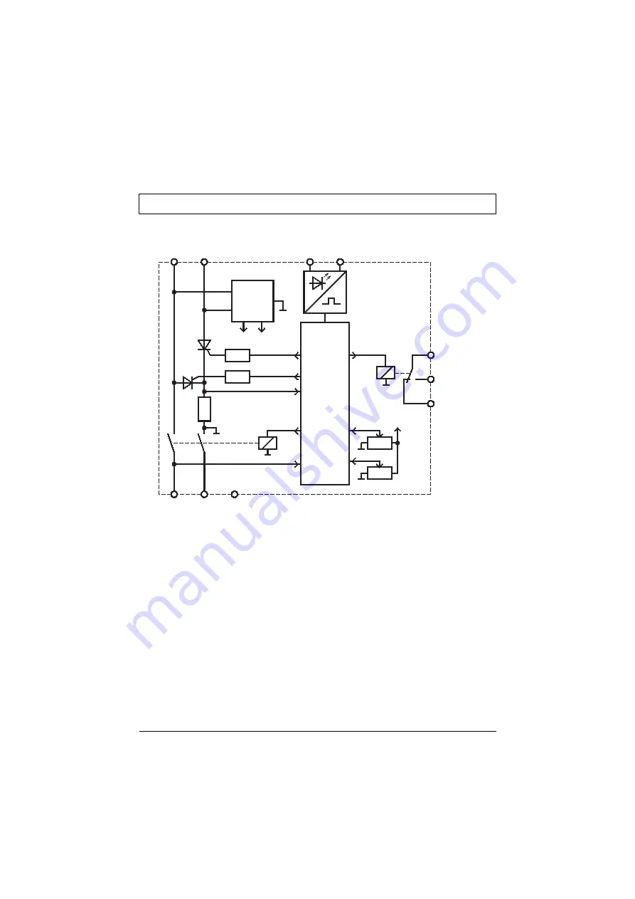
Block diagram
7.
Functional description (see connection diagram)
After the operating voltage on 1L1 and 3L2 has been switched on, the main contactor interlock
X5, X6, the fault signaling contact closes. The motor can be started.
A starting logic makes sure that, when switching the plant on with the master switch while the
motor is still switched off, braking is not initiated.
The fully automatic run of the braking interval starts when the normally closed contact (connected
to the terminals X3, X4) of the motor contactor is reclosed. During braking, the main contactor is
interlocked via the contact X5, X6. After a delay time which, dependent on the amount of the
remanent voltage of the motor, optimizes itself, the integrated braking relay pulls in. After the
contact bounce time has been waited out, a controlled d.c. current is fed into the motor winding.
The magnetic field resulting from this has a braking effect on the still rotating rotor. The d.c.
current is generated by a thyristor phase control. Special suppressor circuits protect the power
semiconductors against overvoltage. With the potentiometer „I“, the braking current (and thus the
braking torque) can be adjusted within a range of 10 … 100% of the rated device current.The
length of time the braking current is to flow can be adjusted with the potentiometer „t“ within a
range of 0...30s/60s. To protect the braking device against overloading in the case of braking
times exceeding 20s, the adjustable maximum braking current (rated device current) decreases.
Controller
1L1
3L2
2T1
4T2
6T3
X5
X6
X3
X4
X7
Interlocking
24V 5V
Power
supply
unit
Braking
time
Braking
current
+5V
Содержание VB 230-25LT
Страница 23: ...22 VB230 400 6 25 30LT...
Страница 24: ...VB230 400 6 25 30LT 23...
Страница 25: ...24 VB230 400 6 25 30LT...
Страница 26: ......


