Stud
Finder
Pencil
1/8 in (3.2 mm)
Wood Drill
Phillips
Screwdriver
Hammer
Level
5/16 in (8 mm)
Concrete Drill
Drill
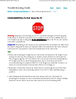
CAUTION!
17.6 lbs.
(8 kg)
DO NOT exceed the maximum weight
indicated. This mounting system is intended
for use only within the maximum weights
indicated. Use with products heavier than
the maximum weights indicated may result
in failure of the mount and its accessories,
causing damage and or injury.
*
*
*
*
*
WARNING! SEVERE PERSONAL INJURY AND PROPERTY DAMAGE CAN RESULT FROM IMPROPER
INSTALLATION OR ASSEMBLY. READ THE FOLLOWING WARNINGS BEFORE BEGINNING.
If you do not understand the instructions or have any concerns or questions, please contact us at
[email protected] (US)/[email protected] (CA).
Do not install or assemble if the product or hardware is damaged or missing. Not all parts and
hardware included must be used. If you require replacement parts, contact customer service at
[email protected] (US)/[email protected] (CA).
Do not attempt to install or assemble this product if the product or hardware is damaged or missing.
The included hardware is designed for use on vertical walls constructed of wood studs or concrete. A
wood stud wall is defined as consisting of a minimum of 2x4 wooden studs (2” width by 4” depth)
with a maximum of 5/8” drywall. The included hardware is not designed for use with metal studs or
drywall. If you’re uncertain about the construction of your wall, then please consult a qualified
contractor or installer for assistance.
For a safe installation, the wall you are mounting to must support 4 times the weight of the total
load. If not, then the surface must be reinforced to meet this standard. The installer is responsible for
verifying that the wall structure and hardware used in any installation method will safely support the
total load.
Weight Restrictions
Tools Needed (Not lncluded)
11
IMPORTANT SAFETY INFORMATION