


(Table 2, contd)
2-7
2
7
3-6
3
6
1-8
1
8
4-5
4
5
2-7
7
2
3-6
6
3
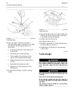
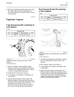
Illustration 7
g06006364
Typical example
5.
Remove the blanking plug in the flywheel housing.
Use Tooling (A) to rotate the crankshaft until the
appropriate mark (4) on the flywheel is in
alignment with the pointers (3). Ensure that there
is clearance between the rocker arm and the
bridgepiece.
Note:
The timing window is located in the flywheel
housing.
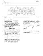
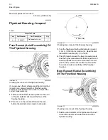
Illustration 8
g01241584
Typical example
6.
Loosen the locknut (7) on the inlet valve bridge.
7.
Hold the top edge of the bridge piece (5). Turn the
adjuster screw (6) down until it contacts the valve.
Note:
When the contact is made with the valve, the
valve must not move. Only the gap between the valve
tip and the bridge piece must be removed.
8.
Tighten the locknut (7) to a torque of 50 N·m
(37 lb ft).
9.
Repeat steps 6 through 8 for the exhaust valve
bridge.
M0064276
19
Содержание 4008-30 SD8
Страница 14: ...Starting System Components 14 M0064276 Electrical System ...
Страница 41: ......
Страница 42: ...M0064276 2015 Perkins Engines Company Limited All Rights Reserved 42 December 2015 ...