background image


Hand-operated boom barriers Type GHS 
Electrically operated boom barriers Type GES 
Electro-hydraulically operated boom barrier Type GEHS 

P

erimeter 

P

rotection 

G

ermany 

G

mbH


Document: 2050274  

Created: 11.04.2011 


Version: a 

Changed: 15.08.2013 

Page 58 of 93 

Original version 

Subject to change 

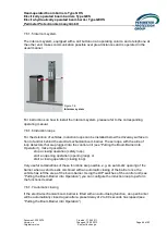
6.2.2.2.4 Automatic closing 
 
You can configure the boom barrier for automatic closing after opening. This automatic mode 
can be activated either by a switch or a button according to the configuration of DIP switch 

S500

. If no button or switch has been installed, you need to permanently activate automatic 

closing using a wire strap between terminals 15 and 17. 


DIP 7 

 
ON / OFF by switch   


ON


ON / OFF by button   


OFF


The timer for automatic closing can be set to between 2 and 90 s using the trimmer. 


6.2.2.2.5 Hold-to-run (dead-man) function 
 
In the normal mode of operation, the boom barrier opens and closes when activated by a 
control device (latch mode). For the closing of the barrier you can activate a hold-to-run 
(dead-man) function with DIP switch 

S500

. The latch mode is thus deactivated and the 

barrier will only close as long as an electric command signal is received. 


DIP 6 

 
Hold-to-run (dead-man) function ON  

ON


Hold-to-run (dead-man) function OFF 

OFF


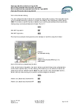
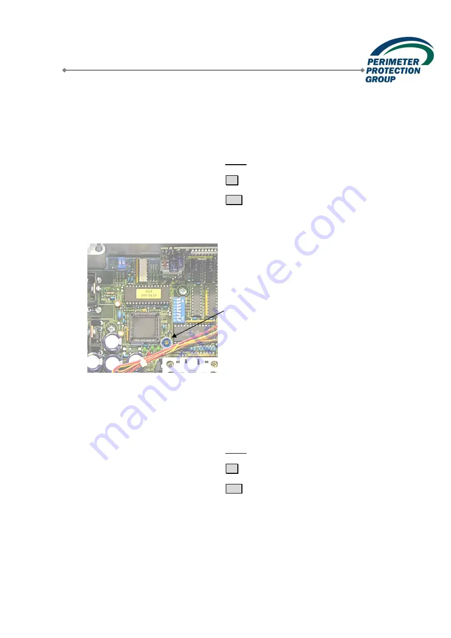
Trimmer 
for automatic closing 


Figure 6.10 

Detailed view of control PCB 

(Figure 6.8) 

with trimmer 
 

Содержание werra GEHS 3

Страница 1: ...iers Hand operated electrically and hydraulically operated boom barriers Hand operated boom barriers Type GHS Electrically operated boom barriers Type GES Electro hydraulically operated boom barriers Type GEHS Perimeter Protection Germany GmbH __________________________________________________________________________ ...

Страница 2: ...rier with fixed support post 5 to 8 m 29 3 9 Electro hydraulically operated barrier with pendulum support 3 to 6 m 31 3 10 Electro hydraulically operated barrier with fixed support post 3 to 6 m 33 4 Transportation and Storage 35 4 1 Transportation 35 4 2 Storage 35 5 Installation of the Boom Barriers 36 5 1 Identification of Components 36 5 2 Preparations 37 5 3 Installation Materials 38 5 4 Inst...

Страница 3: ...nd operated Boom Barriers 62 7 6 Operation of Electrically and Electro hydraulically Operated Boom Barriers 63 7 6 1 Opening and closing 63 7 6 2 Optional safety devices 67 7 7 Operating the Boom Barrier in Case of Power Loss 69 7 7 1 Electro mechanical boom barriers 70 7 7 2 Electro hydraulically operated boom barriers 71 8 Inspection and Maintenance 72 8 1 Maintenance Contract 73 9 Repairs Spare...

Страница 4: ...cess widths Type GHS 2 2 m Type GHS 3 3 m Type GHS 4 4 m Type GHS 5 5 m Type GHS 6 6 m Type GHS 7 7 m Type GHS 8 8 m Electrically operated Type GES Electro hydraulically operated Type GEHS Access widths Access widths Type GES 2 2 m Type GEHS 3 3 m Type GES 3 3 m Type GEHS 4 4 m Type GES 4 4 m Type GEHS 5 5 m Type GES 5 5 m Type GEHS 6 6 m Type GES 6 6 m Type GES 7 7 m Type GES 8 8 m Manufacturer P...

Страница 5: ...systems are not designed for pedestrian passage Note The boom barrier systems are not suited for the integration into a system of escape routes For that purpose our product range includes different gates for pedestrian passage For trouble free opening of the boom barriers in case of an emergency for example by the fire brigade special measures must be taken We will be glad to submit suitable propo...

Страница 6: ...ers are also designed for easy installation and low maintenance 2 2 1 Hand operated boom barriers Hand operated barriers are available with the following standardised blocking widths of 2 m Type GHS 2 3 m Type GHS 3 4 m Type GHS 4 5 m Type GHS 5 6 m Type GHS 6 7 m Type GHS 7 8 m Type GHS 8 As an option these hand operated barriers can be fitted with a pendulum support or a fixed support post We re...

Страница 7: ...led damper used for counterbalancing are located in the barrier stand The stand is fitted with a base plate with drilled holes for bolting it onto a concrete foundation As standard the stand is treated with high quality galvanisation and red powder coating The barrier boom consists of an aluminium tube The tube is tightly sealed with a round plate at the front end to prevent any rain water or othe...

Страница 8: ...om Optional equipment As an option the barrier pole can be supported by means of a pendulum support The pendulum support can be adjusted in height and as an option also be fitted with a shock absorber Instead of the pendulum support we can also supply upon request a fixed support post which is either bolted onto a concrete foundation or set into concrete The support post comes with a rubber coated...

Страница 9: ...8 2013 Page 9 of 93 Original version Subject to change Figure 2 7 Locking bolt for barrier boom Figure 2 8 Lockable locking bolt Locking Different options are available for locking the hand operated boom barriers A locking bolt is used to secure the barrier boom in the open or closed position It can be locked with a padlock The locking bolt is also available fitted with a profile cylinder and or a...

Страница 10: ...y and electro hydraulically operated boom barriers As standard two different versions of the electrically and electro hydraulically operated barriers are available Type Blocking width Type GES 2 2 m Type GES 3 GEHS 3 3 m Type GES 4 GEHS 4 4 m Type GES 5 GEHS 5 5 m Type GES 6 GEHS 6 6 m Type GES 7 7 m Type GES 8 8 m Figure 2 9 Electro mechanical barrier with barrier boom mount on the side GES 2 4 F...

Страница 11: ... the two barriers facing each other On electro mechanical barriers with side mounted barrier booms the barrier boom mounts will then be installed on opposite sides of the barrier housings so as to ensure that the booms are in alignment see Figure 2 11 The one sided or fork mounted barrier boom is made from aluminium and tightly sealed at the open ends so as to prevent any rain water or other dirt ...

Страница 12: ...2 14 Fixed support post for barrier boom Optional equipment On barrier booms of 3 m and more we recommend the use of a mechanical support for the barrier boom As an option the barrier pole can be supported by means of a pendulum support The pendulum support can be adjusted in height and as an option also be fitted with a shock absorber Instead of the pendulum support we can also supply upon reques...

Страница 13: ...d control unit of our electrically and electro hydraulically operated boom barriers is mounted in a self supporting steel frame construction This frame construction has a base plate with holes for fastening it onto a concrete foundation Figure 2 15 Drive and control unit in self supporting steel frame construction The frame construction is covered with a two piece stainless steel casing for easy m...

Страница 14: ...aged which when turning 1800 drives a push rod with the appropriate leverage which in turn raises or lowers the barrier boom by 900 The sinusoidal motion thus generated causes the motion of the barrier boom to start slowly accelerate continuously then decelerate before the boom slowly reaches its final position The electronic control unit is located in a plastic casing and also mounted in the fram...

Страница 15: ...of oil flow Turning the screws to the right increases the degree of dampening while turning the screws to the left decreases it This design principle ensures not only short opening and closing times but also smooth start up and slow down of the boom movement 2 2 2 2 2 Hydraulic power unit The hydraulic power unit is mounted in the barrier stand and consists of the following components oil reservoi...

Страница 16: ... 2 4 Control unit The electronic control unit is located in a plastic casing and also mounted in the frame construction This control unit provides a variety of functions and safety settings 2 2 2 2 5 Limit switch When the final positions open or closed are reached the drive is switched off by means of limit switches The limit switches are located in the barrier housing and are activated by switch ...

Страница 17: ...rotection Germany GmbH Document 2050274 Created 11 04 2011 Version a Changed 15 08 2013 Page 17 of 93 Original version Subject to change Figure 2 21 Limit switching on electro hydraulic barriers Switch cam Open Switch cam Close Figure 2 20 Drive system on electro hydraulic barriers Hydraulic cylinder Hydraulic power unit Limit switch Control unit ...

Страница 18: ...ystem This system can be programmed with many special functions DIP switches allow for easy programming of the control unit A wide range of options is available for controlling and operating the boom barriers to meet various requirements and levels of convenience when opening and closing the barriers onsite with a key or a code card from a gate keeper s lodge using a desk top console with a remote...

Страница 19: ... GEHS Perimeter Protection Germany GmbH Document 2050274 Created 11 04 2011 Version a Changed 15 08 2013 Page 19 of 93 Original version Subject to change Figure 2 26 Desk top console Figure 2 25 Contact free code card reader Figure 2 24 Key switch Figure 2 27 Hand held transmitter for remote controlling Figure 2 28 Intercom system ...

Страница 20: ...lights control the directions of passage o Rotating beacons provide advance warning o Manual operation is possible at all times by means of a hand crank e g in case of a power loss 2 3 Declaration of Conformity Incorporation Note The following text is meant as a sample The original of the declaration for each product will be enclosed with this documentation In accordance with Article 8 of the Mach...

Страница 21: ...GR 232 Rules for Powered Windows Doors and Gates formerly known as ZH 1 494 2 4 Environmental Compatibility Our boom barrier systems do not adversely affect the environment in any way The electric control system of the electro mechanical barriers has been tested and found to be EMC safe electro magnetic compatibility During manufacturing we employ solvent free processes for surface treatment Steel...

Страница 22: ...ight are identical when mirror inverted 3 1 Hand operated boom barrier 2 8 m 3 2 Hand operated boom barrier with pendulum support 2 8 m Type GHS 2 GHS 3 GHS 4 GHS 5 Dimensions S Blocking width 2 m 3 m 4 m 5 m G Total width 2 150 mm 3 150 mm 4 150 mm 5 150 mm B Boom length 1 925 mm 2 925 mm 3 925 mm 4 925 mm Weights Barrier stand 45 kg 45 kg 45 kg 45 kg Barrier boom 4 kg 6 kg 8 kg 10 kg Pendulum su...

Страница 23: ...50 mm B Boom length 5 925 mm 6 925 mm 7 925 mm Weights Barrier stand 47 kg 50 kg 50 kg Barrier boom 12 kg 14 kg 16 kg Pendulum support optional 2 kg 2 kg 2 kg Total weight 61 kg 66 kg 68 kg Colour Stand high quality galvanised and coated in carmine red RAL 3002 Barrier boom aluminium coated in white with red adhesive stripes Optional pendulum support coated in carmine red RAL 3002 Other colours ar...

Страница 24: ...s Barrier stand 45 kg 45 kg 45 kg 45 kg Barrier boom 4 kg 6 kg 8 kg 10 kg Fixed support post optional 25 kg 25 kg 25 kg 25 kg Total weight 74 kg 76 kg 78 kg 80 kg Type GHS 6 GHS 7 GHS 8 Dimensions S Blocking width 6 m 7 m 8 m G Total width 6 320 mm 7 320 mm 8 320 mm B Boom length 6 095 mm 7 095 mm 8 095 mm Weights Barrier stand 47 kg 50 kg 50 kg Barrier boom 12 kg 14 kg 16 kg Fixed support post op...

Страница 25: ...ions S Blocking width 2 m 3 m 4 m G Total width 2 365 mm 3 365 mm 4 365 mm B Boom length 2 325 mm 3 325 mm 4 325 mm Weights Barrier housing 90 kg 90 kg 90 kg Barrier boom 4 7 kg 6 7 kg 8 8 kg Pendulum support optional 2 kg 2 kg 2 kg Total weight 96 7 kg 98 7 kg 100 8 kg Closing time 3 5 s 3 5 s 3 5 s Colour Barrier housing stainless steel hood coated in red RAL 3002 Barrier boom aluminium coated i...

Страница 26: ...26 of 93 Original version Subject to change Electrical data Supply voltage 400 V AC Installed load approx 850 VA Current consumption approx 0 5 A with motor running approx 4 5 A IP rating of control unit IP 54 General data Ambient operating temperature 20 to 45 0 C 3 6 Electrically operated boom barrier with fixed support post 2 to 4 m Figure 3 4 Dimensional drawing electro mechanical boom barrier...

Страница 27: ...ghts Barrier housing 90 kg 90 kg 90 kg Barrier boom 5 kg 7 kg 9 kg Fixed support post optional 25 kg 25 kg 25 kg Total weight 120 kg 122 kg 124 kg Closing time 3 5 s 3 5 s 3 5 s Colour Barrier housing stainless steel hood coated in red RAL 3002 Barrier boom aluminium coated in white with red adhesive stripes Optional fixed support post coated in carmine red RAL 3002 Other colours are available upo...

Страница 28: ...tal width 5 470 mm 6 470 mm 7 470 mm 8 470 mm B Boom length 4 855 mm 5 855 mm 6 855 mm 7 855 mm Weights Barrier housing 148 kg 148 kg 152 kg 152 kg Barrier boom 10 kg 12 kg 14 kg 16 kg Pendulum support 2 kg 2 kg 2 kg 2 kg Total weight 160 kg 162 kg 168 kg 170 kg Closing time 6 s 6 s 9 s 9 s Colour Barrier housing stainless steel hood coated in red RAL 3002 Barrier boom aluminium coated in white wi...

Страница 29: ...width 5 470 mm 6 470 mm 7 470 mm 8 470 mm B Boom length 4 855 mm 5 855 mm 6 855 mm 7 855 mm Weights Barrier housing 148 kg 148 kg 152 kg 152 kg Barrier boom 10 kg 12 kg 14 kg 16 kg Fixed support post 25 kg 25 kg 25 kg 25 kg Total weight 183 kg 185 kg 191 kg 193 kg Closing time 6 s 6 s 9 s 9 s Colour Barrier housing stainless steel hood coated in red RAL 3002 Barrier boom aluminium coated in white ...

Страница 30: ...ted 11 04 2011 Version a Changed 15 08 2013 Page 30 of 93 Original version Subject to change Electrical data GES 5 GES 6 GES 7 GES 8 Supply voltage 400 V AC 400 V AC Installed load approx 550 VA approx 500 VA Current consumption approx 0 5 A approx 0 5 A with motor running approx 3 5 A approx 1 5 A IP rating of control unit IP 54 IP 54 General data Ambient operating temperature 20 to 45 0 C ...

Страница 31: ...m 5 m 6 m G Total width 3470mm 4470mm 5470mm 6470mm B Boom length 2855mm 3855mm 4855mm 5855mm Weights Barrier housing 151 kg 151 kg 151 kg 151 kg Barrier boom 6 kg 8 kg 10 kg 12 kg Pendulum support 2 kg 2 kg 2 kg 2 kg Total weight 159 kg 161 kg 163 kg 165 kg Closing time ca 4 s ca 4 s ca 6 s ca 6 s Colour Barrier housing stainless steel hood coated in red RAL 3002 Barrier boom aluminium coated in ...

Страница 32: ...Germany GmbH Document 2050274 Created 11 04 2011 Version a Changed 15 08 2013 Page 32 of 93 Original version Subject to change Electrical data GEHS 3 6 Supply voltage 400 V AC Installed load approx 1100 VA Current consumption approx 0 5 A with motor running approx 4 4 A IP rating of control unit IP 54 General data Ambient operating temperature 20 to 45 0 C ...

Страница 33: ...mm 4 470 mm 5 470 mm 6 470 mm B Boom length 2 855 mm 3 855 mm 4 855 mm 5 855 mm Weights Barrier housing 151kg 151 kg 151 kg 151kg Barrier boom 6 kg 8 kg 10 kg 12 kg Fixed support post 25 kg 25 kg 25 kg 25 kg Total weight 182 kg 184 kg 186 kg 188 kg Closing time approx 4 s approx 4 s approx 6 s approx 6 s Colour Barrier housing stainless steel hood coated in red RAL 3002 Barrier boom aluminium coat...

Страница 34: ...Germany GmbH Document 2050274 Created 11 04 2011 Version a Changed 15 08 2013 Page 34 of 93 Original version Subject to change Electrical data GEHS 3 6 Supply voltage 400 V AC Installed load approx 1100 VA Current consumption approx 0 5 A with motor running approx 4 4 A IP rating of control unit IP 54 General data Ambient operating temperature 20 to 45 0 C ...

Страница 35: ...ier boom mount As a rule these components will be delivered to the construction site by lorry The barrier stand or the barrier housing are secured onto a Euro pallet and sealed in plastic foil A forklift is required for unloading Warning Be sure to follow the Regulations for Accident Prevention UVV in particular as applicable to working with suspended loads For information on the weights to be mov...

Страница 36: ... version Subject to change 5 Installation of the Boom Barriers 5 1 Identification of Components Hand operated boom barrier Type GHS 2 up to 8 m Electro hydraulically operated boom barrier Type GEHS 3 to 6 m 1 Barrier boom 5 Hood 9 Pendulum support 2 Locking bolt 6 Barrier boom mount 10 Fixed support post 3 Barrier stand 7 Housing front panel 4 Base plate 8 Housing rear panel 1 2 3 4 Options Pendul...

Страница 37: ...proper installation The applicable Accident Prevention Regulations have to be observed 5 2 Preparations Before installation work is started the foundations should be checked using the foundation drawings we enclose If no foundation drawings were supplied please request them from us Note General foundation drawings can easily be found on our website www perimeterprotection net where they are availa...

Страница 38: ...ribed cables for the electro mechanical barriers been properly laid in the conduit o Has the concrete cured completely o Does the quality of the concrete correspond to B 25 5 3 Installation Materials Bolts nuts and plugs for fastening are supplied by us These materials can be found on the barrier boom mount the same applies to any keys if supplied The Operating Manual and the circuit diagrams for ...

Страница 39: ...etal has to be inserted close to the bore holes for the fastening bolts so that the base plate does not deform under tension If the hand operated barrier is provided with a fixed support post you will also have to check that the barrier stand of the hand operated boom barrier is properly aligned with the foundation for the support post The base plate is fastened with the fastening anchors provided...

Страница 40: ...d at the factory Therefore you should not re adjust them 5 5 Installation of the Electrically Operated Boor Barrier Type GES and the Electro hydraulically Operated Boom Barrier Type GEHS Note The electro mechanical boom barriers can optionally be fitted with a pendulum support or a fixed support post The installation of these components is described in sections 5 6 and or 5 7 For lifting and trans...

Страница 41: ...rsion Subject to change Removal of the rear housing panel on GES 2 4 Figure 5 7 Magnetic safety switch mounted on hood and rear panel of housing Figure 5 5 Unlock the housing on the front side push the hood towards the back and remove it by lifting it up left photo GES 2 4 right photo GES 5 8 Figure 5 8 Loosen the 4x M 8 bolts on the inside of the back panel with a socket spanner and remove the re...

Страница 42: ...removed This switch is connected to the control unit by means of a wire Unless you just want to set the rear housing panel aside and keep it in close proximity the cable connection may have to be disconnected Removal of the rear housing panel on GES 5 8 and GEHS 3 6 Now place the electro mechanical barrier without its housing on the foundation Make sure that the cable can be threaded through the r...

Страница 43: ...holes is 18 mm 5 5 2 Aligning Use a water level to check that the stand of the electro mechanical barrier is properly vertical if needed adjust its alignment by inserting pieces of sheet metal close to the drilled holes You should also check the correct position of the barrier when closed If applicable a fixed support post if any has to be taken into consideration when checking the alignment Becau...

Страница 44: ...l mounted on the barrier stand in such a way that the holes for the fastening screws align Put the half shell that was supplied loosely on top of the boom and fasten the screws The electrically operated boom barriers of Types GES 5 8 and the electro hydraulically operated boom barriers of Types GEHS 3 6 have a fork shaped central barrier boom mount Push the barrier boom onto the tube of the boom m...

Страница 45: ... the cables from the conduits have to be connected to the terminal block In any case and while observing all relevant regulations and standards you will have to connect the power supply Depending on the individual version of the electro mechanical barrier additional external components may have to be connected as well desk top consoles induction loops etc If applicable this may also apply to the f...

Страница 46: ...lation of the Pendulum Support As an option our boom barriers can be fitted with a pendulum support for the barrier boom The pendulum support is factory installed The foot of the pendulum support is available in two versions with or without a shock absorber Fastening flange on barrier boom Pendulum support stop Figure 5 18 Fastening the pendulum support Figure 5 20 Pendulum support foot with shock...

Страница 47: ... so that is it properly aligned with the barrier boom If applicable make sure that any cables are threaded through the opening of the post s base plate without being damaged Mark the positions of the fastening holes in the base plate on the concrete foundation The base plate is fastened with fastening anchors You need to drill 12 mm holes into the concrete and insert the fastening anchors using a ...

Страница 48: ...ost so that it is both perfectly vertical and of the correct height then wedge it in place Fill up the sleeve with site mixed concrete and let it cure for the prescribed time 6 Putting the Boom Barrier into Operation Warning Our boom barrier systems may only be put into operation by persons especially authorised by us for this purpose Failure to do so will void the warranty Do not undertake any re...

Страница 49: ...CLOSED position provided the installation was carried out properly Therefore you should not adjust these end stops 3 If a fixed support post is provided for the barrier boom you should check that the boom rests properly in the resting fork of the post in such a way that the support post bears the weight of the boom and not the end stops Figure 6 1 Should that not be the case you have to change the...

Страница 50: ...h all available control devices Note For programming and operating of the code keypad or code cards if any please refer to the separate manuals supplied with them Check the following by visual inspection 1 Does the boom move easily Look for a smooth and low noise operation of the drive 2 Does the drive properly switch off in either final position of the barrier boom 3 Does the barrier come to rest...

Страница 51: ...t Some optional functions can be set or modified on the control unit Important Note All electrical installations may only be carried out by a qualified electrician BGV A2 6 2 2 1 Opening the barrier housing In order to gain access to the control unit and the terminal block you need to remove the housing first Figure 6 4 Unlock the housing on the front side push the hood towards the back and lift i...

Страница 52: ...or safety purposes otherwise control elements in locations not visible from the position of the barrier may trigger a command for boom operation and thus possibly pose a safety hazard If you want to conduct trial runs of the barrier operation you will have to temporarily put back in place the hood with the magnetic safety switch 6 2 2 2 Possible adjustments on the control unit Prior to making any ...

Страница 53: ... boom barrier Type GEHS Perimeter Protection Germany GmbH Document 2050274 Created 11 04 2011 Version a Changed 15 08 2013 Page 53 of 93 Original version Subject to change Figure 6 8 Control unit Plug in socket for induction loop detectors DIP switches see Figure 6 9 Trimmer for automatic closing see Figure 6 10 ...

Страница 54: ...can be selected from two levels The range of permissible frequencies is from 30 to 130 kHz The frequency depends on the loop geometry the number of loops the loop wiring and the frequency level set with the DIP switches We recommend an operating range of 45 to 120 kHz Note In order to determine the optimal frequency setting for the detector you can use our diagnostic device VEK FG2 On an LCD displ...

Страница 55: ...ON Setting the hold time You can set the hold time for each loop separately Loop 1 Loop 2 DIP 3 DIP 7 Hold time infinite ON Hold time 5 minutes OFF LED indicators Each loop detector PCB has one green and one red LED which let you know the state of the loop detector Green LED Red LED No supply voltage OFF OFF Calibration or frequency output FLASHES OFF Detector ready loop is free ON OFF Detector re...

Страница 56: ...o change 6 2 2 2 2 Configuration of the induction loops Up to two induction loops can be connected Each induction loop can be configured with DIP switches Configuration of induction loop 1 with DIP switch S500 DIP 2 DIP 3 Opening loop ON ON Starts opening operation Safety loop ON OFF Stops closing operation Closing loop OFF ON Starts closing operation Loop deactivated OFF OFF DIP switch S501 DIP s...

Страница 57: ... loop OFF ON Starts closing operation Loop deactivated OFF OFF Use DIP switch S501 to set the time after which the barrier is automatically closed once a vehicle has passed the closing loop DIP 1 Auto closing after 3 s ON Auto closing after 1 0 s OFF 6 2 2 2 3 Setting the automatic reversing function If a closing operation is stopped by a photoelectric barrier or an induction loop automatic reopen...

Страница 58: ...rmanently activate automatic closing using a wire strap between terminals 15 and 17 DIP 7 ON OFF by switch ON ON OFF by button OFF The timer for automatic closing can be set to between 2 and 90 s using the trimmer 6 2 2 2 5 Hold to run dead man function In the normal mode of operation the boom barrier opens and closes when activated by a control device latch mode For the closing of the barrier you...

Страница 59: ...oom barrier close after passage of a vehicle 3 Does the barrier close automatically after having been opened provided automatic closing is activated 4 Does the advance warning time set if any cause the barrier to close after a time delay has lapsed 5 Does the activation of the safety function safety pressure strip or photoelectric barrier cause the boom barrier to immediately stop any closing oper...

Страница 60: ...amage to persons or property please follow all information and warning hints contained in this Operating Manual these hints are an important part of our warranty When operating electric devices certain components contain as a matter of course dangerous voltage Therefore do not remove any covers Any installation and maintenance work must be carried out by qualified and knowledgeable personnel This ...

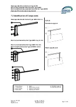
Страница 61: ...o change 7 2 Identification of Components Hand operated boom barrier Type GHS 2 to 8 m Electro mechanical barrier Type GES 2 up to 4 m Electro mechanical barrier Type GES 5 to 8 m Electro hydraulic barrier Type GEHS 3 to 6 m 1 Barrier boom 5 Hood 9 Pendulum support 2 Locking bolt 6 Barrier boom mount 10 Fixed support post 3 Barrier stand 7 Housing front panel 4 Base plate 8 Housing rear panel 1 2 ...

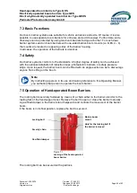
Страница 62: ...tandards A higher degree of safety can be achieved with the optional installation of induction loops photoelectric barriers or safety pressure strips Upon request the barrier boom can be fitted with an angle section so as to discourage anyone from sitting on the boom Note By instructing a person in its use and making reference to this Operating Manual you authorise that person to operate the boom ...

Страница 63: ...low properly instructed persons to operate our electrically operated boom barriers You can operate the electrically and electro hydraulically operated boom barriers with a variety of control devices It may also prove very useful to employ a combination of different control devices Please ascertain which product version you ordered Note No matter what type of control device you use to operate the e...

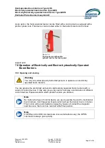
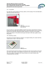
Страница 64: ...losing of the barrier There is no need to keep the key turned in the respective direction instead you can return it to the middle position and remove it The electric control system will switch off the drive system in either final position 7 6 1 2 Desk top console The desk top console will ideally be installed in a reception building The console has three function buttons Open Stop and Close If the...

Страница 65: ...te controlled person dependent entrance control system You operate the code keypad by entering a programmed number For programming the code keypad please refer to the corresponding separate operating manual 7 6 1 4 Code card With a code card a contact free swipe type person and or time dependent entrance control system can be achieved The code card reader is operated in the usual manner For progra...

Страница 66: ...ctro mechanical boom barrier These loops with the aide of loop detectors that are plugged into the control unit see Putting the Boom Barrier into Operation make it possible to stop a closing operation safety loop start an opening operation opening loop or start a closing operation closing loop Very useful combinations of these functions are possible e g an automatic opening of the barrier when a v...

Страница 67: ...one or more safety pressure strips can be mounted on the boom The safety pressure strips protect the barrier boom against slamming into an obstacle If a safety pressure strip is activated the closing operation is immediately interrupted In addition the barrier s control unit can be configured for automatic opening of the barrier auto reversing in such an event see Putting the Boom Barrier into Ope...

Страница 68: ...GEHS Perimeter Protection Germany GmbH Document 2050274 Created 11 04 2011 Version a Changed 15 08 2013 Page 68 of 93 Original version Subject to change either direction For the operation of these warning devices an advance warning time of 3 seconds can be set on the barrier control unit see Putting the Boom Barrier into Operation ...

Страница 69: ...r supply However you can also open or close our electro mechanical boom barriers by hand For this purpose you need to remove the housing the photos show the stainless steel housing in the as delivered state i e still covered in the protective film The hood is fitted with a magnetic safety switch which disables all electrical functions once the hood has been removed Nevertheless you should turn off...

Страница 70: ...ation to the control unit However it may be that the time out function has switched off the drive This could happen because of some mechanical obstacle preventing the barrier boom from reaching its final position during opening or closing Once the obstacle has been removed you can resume normal operation of the barrier by switching the control unit off and on again 7 7 1 Electro mechanical boom ba...

Страница 71: ...pose the three way valve must be switched from the middle position normal operation to the position manual lifting The barrier boom can now be brought by hand into any position desired and it will remain in that position In case of a power loss and with the barrier open the three way valve is to be set to manual lowering which will cause the barrier boom to lower due to its own weight Note Please ...

Страница 72: ...nt on some units 1 Drive unit o Are the motor mountings securely fastened o Check noise and tightness of motor and gearbox o Check function and ease of operation of the emergency release o Check proper tension and secure mounting of the spring o Is the push rod properly adjusted On electro hydraulically operated boom barriers the following items actions are to be checked performed o Check hydrauli...

Страница 73: ...tings of the traffic detectors o Check the induction loops for proper function and grounding o Check the condition of all power supply and control leads o Are all plug in and clamp connections correct and fastened securely 4 Miscellaneous o Documentation of inspection and or maintenance work 8 1 Maintenance Contract The maintenance contract which we offer is a good and efficient solution to ensure...

Страница 74: ...boom barriers Type GES Electro hydraulically operated boom barrier Type GEHS Perimeter Protection Germany GmbH Document 2050274 Created 11 04 2011 Version a Changed 15 08 2013 Page 74 of 93 Original version Subject to change Annex 1 Spare parts for Type GES 2 4 ...

Страница 75: ...ulically operated boom barrier Type GEHS Perimeter Protection Germany GmbH Document 2050274 Created 11 04 2011 Version a Changed 15 08 2013 Page 75 of 93 Original version Subject to change Art no 202565 Art no 29345 CONTROL UNIT TST WI 1 0 FP TRAFFIC DETECTOR TST with EPROM without casing SVEK1 D ...

Страница 76: ...Created 11 04 2011 Version a Changed 15 08 2013 Page 76 of 93 Original version Subject to change Art no 29346 Art no 302217 TRAFFIC DETECTOR TST SVEK2 D RING FOR HT 50 202564 MICRO PROCESSOR WI F V 05 01 01 barrier control unit Art no 300472 Art no 300473 GEARED MOTOR GES 2 4 10 1 min 400V GEARED MOTOR GES 2 4 10 0 37D2CRMI40 63I 1 280KWST Type 1 min 230V Type 0 55W2CRMI40 63I 1 280KWST ...

Страница 77: ...ment 2050274 Created 11 04 2011 Version a Changed 15 08 2013 Page 77 of 93 Original version Subject to change Art no 202466 Art no 85151 Heater 20W Thermostat for heater Art no 300481 Art no 300474 LIMIT SWITCH BARRIER MAGNETIC SWITCH GES Magnet with mounting bracket MK 13 1A66 C 1000X Art no 300494 Art no 300495 HAND CRANK FOR BARRIER GES ROTATING HANDLE M10 DIN 98 KT 25 E ...

Страница 78: ...hanged 15 08 2013 Page 78 of 93 Original version Subject to change Art no 300907 Art no 300906 HOOD FOR BARRIER HOUSING GES2 4 BARRIER HOUSING GES 2 4 stainless steel bolted RAL 3002 stainless steel without hood Art no 302086 Art no 302087 HOUSING FRONT PANEL GES2 4 HOUSING REAR PANEL GES2 4 stainless steel stainless steel Art no 300594 Art no 300608 STAND FOR BARRIER GES 2 4 PLATE FOR CABLES GES ...

Страница 79: ...1 Version a Changed 15 08 2013 Page 79 of 93 Original version Subject to change Art no 300606 Art no 300607 BRACKET 2 for CONTROL UNIT GES2 3 4 RETAINING PLATE 1 CONTROL UNIT GES 2 3 4 rear front Art no 300605 Art no 300602 SHAFT FOR PUSH ROD GES 2 4 SWIVEL LEVER WITH SHAFT GES 2 4 complete Art no 82517 Art no 300502 PEDESTAL BEARING UCP 206 CLEVIS WITH FOLDING SPRING BOLT for pendulum support GER...

Страница 80: ...ted 11 04 2011 Version a Changed 15 08 2013 Page 80 of 93 Original version Subject to change Art no 825656 Art no 84670 JOINT HEAD ES1 3 RIGHT JOINT HEAD ES1 3 LEFT Type EM 12 R Type EM 12 L Art no 250267 Art no 300399 FEATHER KEY DIN 6885 8 x 7 x 56 FITTING BOLT M 10x35 possible for barriers manufactured until 2003 Art no 80292 Art no 203674 FITTING BOLT M 10x20 MAGNET FOR REED SENSOR RECT ...

Страница 81: ...mbH Document 2050274 Created 11 04 2011 Version a Changed 15 08 2013 Page 81 of 93 Original version Subject to change Art no 67588 Art no 67541 BARRIER BOOM WEGO ø 80 MM PEND SUPPORT w o shock absorber RAL 3002 302081 PEND SUPPORT COMPLETE RAL 3002 with shock absorber Art no 302442 Art no 301099 BRACKET FOR PEND SUPPORT BRACKET FOR PEND SUPPORT coated hot galvanised ...

Страница 82: ...0274 Created 11 04 2011 Version a Changed 15 08 2013 Page 82 of 93 Original version Subject to change Art no 301073 Art no 300909 BRACKET FOR BARRIER SKIRT LATCH FOR LOCKING CYLINDER for 80 barrier boom barrier GES Art no 204362 Art no 202314 CYLINDER LATCH LOCK EMKA KEY EK 333 Art no 300601 Art no 300446 BARRIER BOOM MOUNT GES 2 4 HALF SHELL BOOM MOUNT GES2 4 galvanised galvanised ...

Страница 83: ...ated boom barrier Type GEHS Perimeter Protection Germany GmbH Document 2050274 Created 11 04 2011 Version a Changed 15 08 2013 Page 83 of 93 Original version Subject to change Art no 302064 Art no 302056 BARRIER BOOM MOUNT GES 2 4 HALF SHELL BOOM MOUNT GES2 4 coated coated Annex 2 Spare parts for Type GES 5 8 ...

Страница 84: ...m barrier Type GEHS Perimeter Protection Germany GmbH Document 2050274 Created 11 04 2011 Version a Changed 15 08 2013 Page 84 of 93 Original version Subject to change Art no 202565 Art no 29345 CONTROL UNIT TST WI 1 0 FP TRAFFIC DETECTOR TST SVEK1 D Art no 202564 MICRO PROCESSOR WI F V 05 01 01 barrier control unit ...

Страница 85: ...3 Original version Subject to change Art no 29346 Art no 300791 TRAFFIC DETECTOR TST SVEK2 D GEARED MOTOR GES 5 6 6 2 1 min 400V Type 0 25D4CRMI40 70I 1 225KWST Art no 300792 Art no 301230 GEARED MOTOR GES 5 6 6 2 1 min 230V GEARED MOTOR GES 7 8 3 0 1 min 400V Type 0 37W4CRMI40 70I 1 225KWST Type 0 25D4 RM40 70I 1 420KWST Art no 300474 Art no 300481 MAGNETIC SWITCH GES 2 6 LIMIT SWITCH BOOM BARRIE...

Страница 86: ...nged 15 08 2013 Page 86 of 93 Original version Subject to change Art no 300494 Art no 300495 HAND CRANK FOR BARRIER GES ROTATING HANDLE M10 DIN 98 KT 25 E Art no 300875 Art no 305789 BARRIER HOUSING GES 5 8 HOOD BARRIER HOUSING GES5 8 made from 1 4301 K240 w o hood made from 1 4301 K240 bolted special order Art no 302088 Art no 302089 HOUSING FRONT PANEL GES5 6 HOUSING REAR PANEL GES5 6 stainless ...

Страница 87: ...11 Version a Changed 15 08 2013 Page 87 of 93 Original version Subject to change Art no 300960 Art no 300882 STAND FOR BARRIER GES 5 8 BUSH FOR SWIVEL ARM ES 5 8 hot galvanised galvanised Art no 302444 Sach Nr 203674 BUSH FOR SWIVEL ARM 5 8 MAGNET FOR REED SENSOR RECT powder coated Art no 300885 Art no 301138 SWIVEL LEVER SHAFT ES 5 8 SWIVEL ARM LONG FOR MOTOR galvanised with pin completely galvan...

Страница 88: ...ion a Changed 15 08 2013 Page 88 of 93 Original version Subject to change Art no 300910 Art no 300971 PUSH ROD FOR GES 5 6 SHAFT FOR SPRING MOUNT TOP GES 5 8 old design until October 2002 galvanised Art no 300962 Art no 300974 PUSH ROD FOR GES 5 8 SPACER SLEEVE SPRING MOUNT GES 5 8 stainless steel galvanised Art no 300958 Art no 300957 JOINT HEAD GES 5 8 LEFT JOINT HEAD GES 5 8 RIGHT Type EM 15 L ...

Страница 89: ...ated 11 04 2011 Version a Changed 15 08 2013 Page 89 of 93 Original version Subject to change Art no 300911 Art no 300912 FLANGE BUSH BARRIER GES 5 6 J F M FLANGE BUSH BARRIER GES 5 6 J F M Art no 300969 Art no 300970 SPRING MOUNT TOP GES 5 8 PLATE FOR CABLES GES 5 8 galvanised galvanised Art no 300973 Art no 301008 MOUNTING BRACKET CONTROL UNIT SPRING FOR GES 5 8 MTS 6 GES 5 8 galvanised ...

Страница 90: ...2011 Version a Changed 15 08 2013 Page 90 of 93 Original version Subject to change Art no 301065 Art no 301066 BRACKET HOUSING TOP GES 5 8 BRACKET HOUSING BOTTOM GES 5 8 right left right version Art no 301087 Art no 301426 BRACKET HOUSING BOTTOM GES 5 8 BUSH FOR SPRING MOUNT 5 8 left version galvanised Art no 302216 Art no 302274 ROLL RING FOR HT 40 COUNTERSUNK BOLT W HEX SOCKET M12 x 40 DIN 7991 ...

Страница 91: ...ion Germany GmbH Document 2050274 Created 11 04 2011 Version a Changed 15 08 2013 Page 91 of 93 Original version Subject to change Art no 66885 Art no 80382 FEATHER KEY FORM A 8x7x40 HEXAGON BOLT M8x120 DIN933 A2 Art no 82517 Art no 300909 PEDESTAL BEARING UCP 206 LATCH FOR LOCKING CYLINDER Art no 204362 Art no 202314 CYLINDER LATCH LOCK EMKA KEY EK 333 ...

Страница 92: ...GmbH Document 2050274 Created 11 04 2011 Version a Changed 15 08 2013 Page 92 of 93 Original version Subject to change Art no 302060 Art no 302061 SWIVEL ARM GES 5 8 BES BARRIER BOOM MOUNT GES 5 8 BES coated coated Art no 204316 Art no 67541 BARRIER BOOM WEGO ø 100 MM PEND SUPPORT w o shock absorber RAL 3002 302081 PEND SUPPORT COMPLETE RAL 3002 with shock absorber ...

Страница 93: ...ted 11 04 2011 Version a Changed 15 08 2013 Page 93 of 93 Original version Subject to change Art no 301099 Art no 302442 BRACKET FOR PEND SUPPORT BRACKET FOR PEND SUPPORT hot galvanised coated Art no 300502 Art no 301072 CLEVIS WITH FOLDING SPRING BOLT BRACKET F BARRIER SKIRT for pendulum support GERMF 12 for 100 barrier boom Art no 302553 BOOM SHAFT COMPLETE GES 5 8 incl pedestal bearings ...

Отзывы: