TTR-08A Electromechanical Tripod Turnstile
10 MAINTENANCE
The turnstile housing maintenance is required once a year or in case of some technical
failures. The maintenance should be carried out by qualified mechanic only.
Caution!
Prior to the turnstile maintenance works disconnect the turnstile power supply
from the AC mains.
The turnstile maintenance works should be carried out in the following order:
1. Switch off the turnstile power supply. The barrier arm will automatically fall down at
that.
2. Unscrew 3 M8 screws to remove the hub with the barrier arms.
3. Check security of mounting of the barrier arms (3) to the hub and if needed, tighten
the barrier arms fixing screws (3).
4. Lubricate the friction units of the barrier arm drop mechanism (automatic folding of
barrier arm “anti-panic”) and barrier arms hinged connections to the hub with
Energrease L21 M
or similar lubricant.
5. Remove the cover (2) with LED indication block from the turnstile housing. The
order is given in Chapter 6.
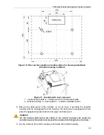
6. Remove the reinforcement plate (Fig. 11). In order to do this, loosen 4 screws,
which are fixing the plate.
7. Check visually the resetting device (pusher, springs and roller), the arm rotation
sensors and the damper (Fig. 14).
Caution!
Avoid the ingress of lubricant on the arm rotation sensor disc and the roller
surfaces.
8. Remove dust from the arm rotation sensor disc, located in the spacing of the arm
rotation optical sensors, with alcohol-gasoline blend applied with a cloth. Avoid the
ingress of dust on the operational spacing of the both arm rotation optical sensors.
9. Lubricate friction joints of the turnstile mechanism in the following points:
a. with
Chain and Rope Lube Spray - WEICON
lubricate the rotation axis of the
stoppers (1,2), roller (3) and the pusher arm (5, Fig. 14);
b. with
Energrease L21 M
or similar lubricant treat the resetting mechanism springs
fixing points (4, 6);
c. with
Chain and Rope Lube Spray - WEICON
lubricate passageway emergency
unlocking mechanism details.
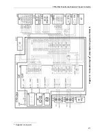
10. Check the reliability of the cable connections to the CLB connector blocks and
XS1
out connector block and if necessary tighten the cable fixing screws.
11. Install the reinforcement cover in reverse order
12. Connect the
S1
cable connector of the indication board to the CLB and mount the
cover with LED display (2) back into its place in the reverse order to the
dismantling. When the cover mounting is carried out correctly it does not need
much effort.
13. Install the hub (5) with barrier arms (3) as indicated in section 8.4
27
Содержание TTR-08A
Страница 34: ...www perco com...


