


20
21
-1
1
8
Power Supply PS1000-A6-48.5
Installation Requirements
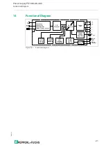
4
Installation Requirements
This device may only be installed and put into operation by qualified personnel.
This device does not contain serviceable parts. The tripping of an internal fuse is caused
by an internal defect. Do not replace the fuse.
If damage or malfunction should occur during installation or operation, immediately turn power
off and send unit to the factory for inspection.
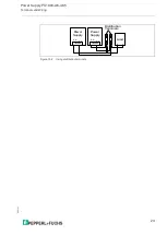
Mount the unit on a DIN-rail so that the input terminals are located on the bottom of the unit.
For other mounting orientations see de-rating requirements in this document.
See chapter 25.11.
This device is designed for convection cooling and does not require an external fan.
Do not obstruct airflow and do not cover ventilation grid (e.g. cable conduits) by more
than 15%!
Keep the following installation clearances: 40mm on top, 20mm on the bottom, 5mm on the left
and right sides are recommended when the device is loaded permanently with more than 50%
of the rated power. Increase this clearance to 15mm in case the adjacent device is a heat
source (e.g. another power supply).
A disconnecting means shall be provided for the output of the power supplies when used
in applications according to CSA C22.2 No 107.1-01.
Warning!
Risk of electrical shock, fire, personal injury or death.
•
Do not use the power supply without proper grounding (Protective Earth).
Use the terminal on the input block for earth connection and not one of the screws
on the housing.
•
Turn power off before working on the device. Protect against inadvertent re-powering.
•
Make sure that the wiring is correct by following all local and national codes.
•
Do not modify or repair the unit.
•
Do not open the unit as high voltages are present inside.
•
Use caution to prevent any foreign objects from entering the housing.
•
Do not use in wet locations or in areas where moisture or condensation can be expected.
•
Do not touch during power-on, and immediately after power-off.
Hot surfaces may cause burns.
Warning!
Explosion hazards
•
Substitution of components may impair suitability for this environment.
•
Do not disconnect the unit or operate the voltage adjustment or S/P jumper unless power
has been switched off or the area is known to be non-hazardous.
•
A suitable enclosure must be provided for the end product which has a minimum
protection of IP54 and fulfils the requirements of the EN 60079-15:2010.
Note
If you use the device
in hazardous areas, observe the safety information in the instruction
manual and in chapter 22.


