Functional Safety M-LB-(Ex-)2000-System
Application Examples
201
9-02
19
7
Application Examples
This chapter shows how to integrate a surge protection barrier into a safety loop.
Integration of a Surge Protection Barrier into a Safety Loop
To define and calculate the safety relevant values for a low demand safety loop,
you have to determine the following basic parameters first:
1. the signal characteristic of the safety loop: analog or digital,
2. the signal direction of the safety loop as seen from the perspective of the safety-rated
programmable logic controller (SPLC): input or output,
3. the safe state of the field device allocated to the surge protection barrier,
4. the mode of operation: low demand mode, high demand mode or continuous mode
5. the required SIL level of the safety loop.
After the safety loop is defined, assign a surge protection barrier to the field device.
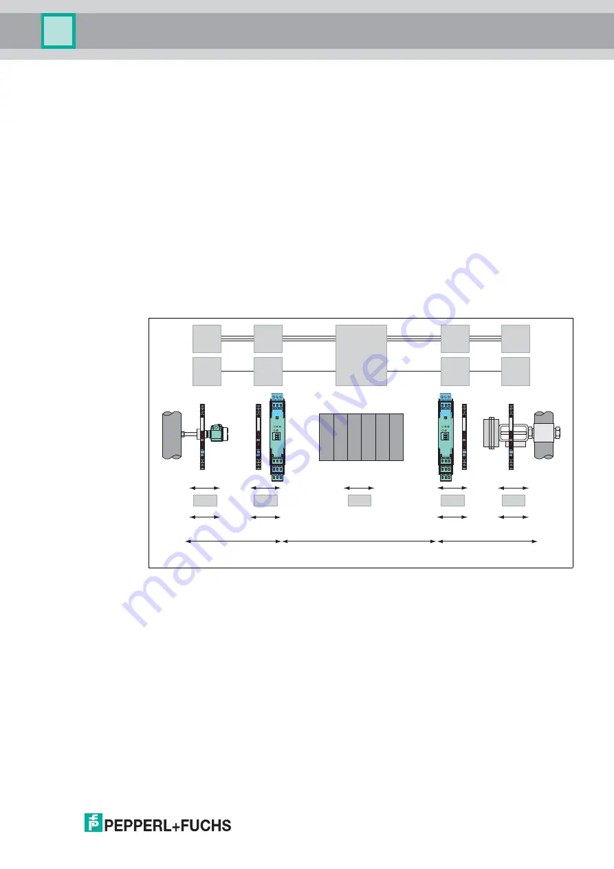
Create a basic overview as shown below.
Figure 7.1
Example of a complete safety loop with assigned surge protection barriers
In principle, the performance values of the surge protection barriers have to be added
to the performance values of the field device or the safety-rated programmable logic controller
(SPLC). By doing so, it is assumed that the surge protection barrier is a part of this device.
Verify with these new values if the necessary SIL level can be achieved.
You find examples of the various applications in the following section.
PFD
1
PFD
3
PFD
2
PFD
5
PFD
4
+
+
+
+
1
3
4
6
2
5
13
15
12
9
10
7
14
11
8
1
2
OUT CHK PWR
S2
S1
S3
II
I
1
3
4
6
2
5
13
15
12
9
10
7
14
11
8
1
2
OUT CHK PWR
S2
S1
S3
II
I
1
2
3
4
5
6
1
2
3
4
5
6
1
2
3
4
5
6
1
2
3
4
5
6
40 %
25 %
Logic system
Sensor
Digital
input
Actuator
Digital
output
Analog
input
Sensor
Analog
output
Actuator
10 %
Signal path
10 %
Signal path
15 %
SPLC
50 %
Actuator and signal path
35 %
Sensor system and signal path


