2
014-
05
16
LS680-DA
Installation
Mounting on a P+F adjustment device
The mounting accessories (OMH-LS610-01) consist of a mounting bracket and
an integral alignment device (in x and y axes). The required beam direction (
±
90
°
rotation) can be set using the mounting accessories, which are fastened to the
mounting bracket using two M4 screws and the central M6 screw. The central
screw is for securing the unit in place following adjustment and should not be
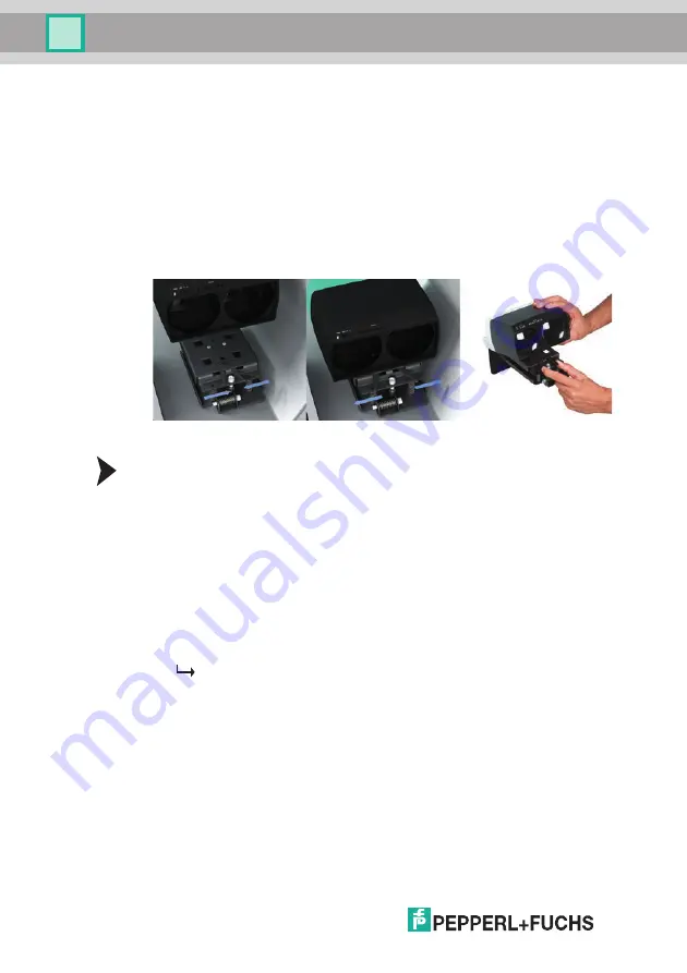
tightened until the adjustment is finalized. To mount the optical data coupler,
squeeze the two front levers together and place feet into the four openings in the
adjustment device. The feet have to lock into place so that the levers can be
released outwards as far as the stop; if necessary the optical data coupler has to
be pressed down applying some force from the top to the center.
5.3
Connection
Connecting the power supply
The device conforms to protection class III. This means that the power has to be
supplied as a low protective voltage (PELV) and limited according to UL Class 2
(100 W). The power supply of the optical data coupler is a 18 V to 30 V DC. The
dielectric test voltage (shield against power/GND) is 50 V maximum.
To supply power to the sensor, proceed as follows:
1. Plug the 4-pin M12 mating cordset into the connector on the rear of the hous-
ing.
2. Screw the cap nut as far as it will go over the connector. This ensures that the
power cable cannot be inadvertently pulled out.
3. Now connect the supply voltage to the cable provided.
The sensor is now ready for operation.


