


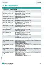


Direct connection of the base station without plug/coupling to
the power module with USB interface
10 5 1
Figure 19. RJ45 plug - connection layout
Base station cordset
Cordset assignment
Power module terminal compart-
ment
rJ45 pinout
Strand color
Designation
Assignment
2
Green
D+2SL
X9
10
White
D-2SL
X10
X11
4
Black
GND
X12
7
Brown
+UB
X13
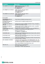
Figure 20. Intrinsically safe terminal compartment of the power module after removing the connector connecti-
on cores
Note
Information relating to programming from the SICK AG manual (www.SICK.com) is
required for the complete commissioning of the handheld scanner.
1
2
3
4
5
BK
BN
WH
GN
6
7
8
9
10
26
C
ommIssIonIng
20
18
-0
6