Pentair PCFE40P12 Скачать руководство пользователя страница 9

Copyright© Pentair

9

_________________________________________________________________________________________________________________________________________

4. INSTALLATION INSTRUCTIONS

________________________________________________________________________________________________________________________________________

4.1 Precautions

The following conditions are required for the installation of the carbon filter system:

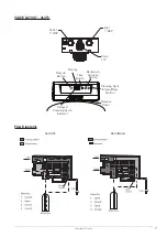
•  Installation and working space : Not less than 350x 350 mm, 170 cm high

•  Distance between centers of inlet and outlet: 10.2cm

•  Distance between power source and carbon filter: No greater than 2m.

•  Level platform or floor.

•  Constant electrical supply to operate the controller.

•  Total minimum pipe run to water heater of ten feet (three meters) to prevent backup of hot 

water into system.

•  Local drain or tub for discharge as close as possible.

•  Water line connections with shutoff or bypass valves.

•  Must meet any local and state codes for site of installation.

•  Valve is designed for minor plumbing misalignments. Do not support weight of system on 

the plumbing.

•  Be sure all soldered pipes are fully cooled before attaching plastic valve to the plumbing.

•  Room to access equipment for maintenance and adding media to tank.

•  After some maintenance work on pipe network, the initial effluent from the faucet often 

contains a lot of rust and pollutants. Therefore, after each occasion of water supply 

stoppage, please open the bypass valve or bypass pipe to drain out dirty water; or install a 

filter before this filter system to ensure that only clean water will enter the water filtration 

system. Generally, influent turbidity should be controlled at less than 5NTU.

•  Generally, the carbon filter is installed after the water meter at the entrance of indoor tap 

water; the water meter can then be used as a gauge for determining the amount of water 

treated.

•  Hot water can cause damage to the internal processing system of the carbon filter. Users 

who connect hot water boiler or instant water heater after the carbon filter must install a 

check valve between the carbon filter and their water heating system, and ensure that their 

water heating system is equipped with temperature and pressure control safety devices.

•  When installing carbon filter in newly renovated premises where water has not been 

used before, first open the water faucet to discharge the water for at least 10 minutes to 

completely flush away any construction debris, corrosion rust and dirt. This will prevent 

dirt from entering the connected carbon filter during installation and cause damages to 

internal filter materials.

•  A manual valve should be installed just before the inlet and outlet respectively. A bypass 

valve or bypass pipe should be installed between the inlet and outlet to facilitate normal 

water usage during maintenance of the carbon filter, or to enable direct usage of non-

treated water when needed. 

•  It is recommended that a pre-filter be installed before the inlet to prevent contaminated 

water from entering the carbon filter system, thus affecting its operation.

•  As much as possible, reduce the length and curvature of the drain line. Always allow an 

air gap between the drain line and the wastewater to prevent the possibility of wastewater 

being back-siphoned into the carbon filter. No valve of any type should be installed along 

the drain line.

Содержание PCFE40P12

Страница 1: ..._________ OWNER S MANUAL Should you the installer or owner be unfamiliar with the correct installation or operation of this type of equipment you should contact the distributor manufacturer for the co...

Страница 2: ..._________ 1 Precautions and General Notes 3 2 Parts Included 4 3 Product Information 5 3 1 Product Features 5 3 2 Specifications 5 3 3 Schematic Diagrams 6 3 4 Introduction to Main Parts 8 4 Installat...

Страница 3: ...the bypass It is not recommended to use sealants on the threads Use Teflon tape on all threaded connections Teflon is a trademark of E I duPont de Nemours General Observe all warnings that appear in...

Страница 4: ...________________________________________ Open the package and ensure that all parts are provided All models of carbon filter contain the following parts 1 Carbon filter with automatic control valves 2...

Страница 5: ...ters use Chlorinated city water as the inlet water they are suitable for filtration treatment of potable water in places with high daily water demand such as homes hotels guesthouses and restaurants 3...

Страница 6: ..._______________________________________________ 3 3 Schematic Diagrams Electrical Control Diagram Drain Inlet Outlet Media Tank Riser Tube Activated Carbon Gravel Optical Sensor 220VAC 12VAC Socket 1...

Страница 7: ..._________________________________________________________________ VALVE LAYOUT 363TC Flow Diagrams SERVICE BACKWASH Recycle Button Time Button Remove Cover Backwash Duration Button Cleaning Cycle Inte...

Страница 8: ...l 3 5 mm 8kg KDF Copper zinc alloy Diameter 0 149 2mm PCFE40P12 500g PCFE54P12 600g Polyethylene PE Media Tank Lining Polyethylene Diameter 250mm 1 piece Housing Fiberglass Height PCFE40P12 Model 1020...

Страница 9: ...ter the water filtration system Generally influent turbidity should be controlled at less than 5NTU Generally the carbon filter is installed after the water meter at the entrance of indoor tap water t...

Страница 10: ...r the better to perform a backwash for several hours This is to ensure optimal performance of the filtration system when restarted In the event of occasional water stoppage or power outage one should...

Страница 11: ...stable Wrench Tube 100 Silicone Grease 4 3 Installation Steps The Carbon filter has three openings the inlet the outlet and drain Open the water supply tap and flush the water pipe network to ensure w...

Страница 12: ...he system to the plumbing leaving the system Water Line and Bypass Connection Once you have selected your location check the direction of the water flow in the main pipe A bypass valve system should b...

Страница 13: ...gure below Wrap the threaded end of the flow controller with Teflon tape Tighten the two components of drain connector kit by hand Insert the drain connector kit onto the drain opening of the carbon f...

Страница 14: ...MIN is displayed the value in minute increments MIN is displayed during Backflush the value displayed is the minutes of Backflush remaining 3 Colon double dots flashes as part of the time display It...

Страница 15: ...minutes will reset to zero when the hours are changed 2 Backwash Duration Press Backwash Duration to display and set the current backwash cycle steps The value in minutes will be displayed for five se...

Страница 16: ...hed for five seconds the controller returns to normal operation mode Pushing the Backflush button immediately returns the controller to normal operation Quick Cycling Press and hold for three seconds...

Страница 17: ...ck the Troubleshooting section Initial Power Up Display When the camshaft has reached the HOME service position the display will show If the time of day alternating with filtered water volume is displ...

Страница 18: ...placed into operation Please review MANUALLY INITIATING A CLEANING CYCLE before attempting startup 1 With the supply water for the system still turned off position the bypass valve to the not in bypas...

Страница 19: ...owner s installation manual Follow all safety guidelines in the manual If metal pipe was used did you restore the electrical ground Securely install drain hose to an approved drain Perform a leak tes...

Страница 20: ...or Diagnosis and Troubleshooting System Error Codes Problem Possible Cause Solution Flowing or dripping water at drain after cleaning cycle Debris is preventing 3 or 4 valve disc from closing Remove d...

Страница 21: ...ce position Camshaft is not turning during E3 display Check that motor is connected Verify that the motor wire harness is connected to motor and controller module Verify that optical sensor is connect...

Страница 22: ...ntair will deem the warranty to have expired and charge the relevant fees 4 Warranty will be void in the following conditions Installation by personnel who are not authorized by the Pentair Product ma...

Страница 23: ...______________________________________________________________________ 7 MAINTENANCE RECORDS ___________________________________________________________________________________________________________...

Страница 24: ...67685900 Thialand 16 Floor The Ninth Towers Grand RAMA 9 Tower B 33 4 Rama 9 Road Huaykwang Bangkok 10310 Thailand Tel 662 1681092 Philippines 5th Floor MAIA Suites 1747 Nicanor Garcia Street Corner D...

Отзывы: