

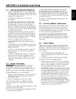


7
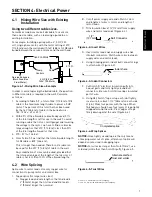
4.1 Mixing Wire Size with Existing
Installation
Using two different cable sizes.
Sometimes conditions make it desirable to use more
than one size cable, such as replacing a pump in an
existing installation.
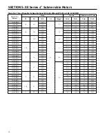
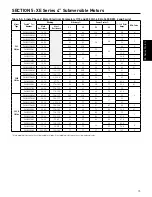
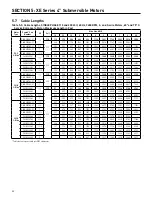
For example: Installing a pump with a 4”, 5 HP, 230
volt, single phase motor, with the motor setting at 370’
(112.8 m) down the well and with 160’ (48.8 m) of #8 cable
buried between the service entrance and the well head.
In order to avoid replacing the buried cable, the question
is: What size cable is required in the well? Calculate
as follows:
1. According to Table 5-9, a total of 326’ (112.8 m) of #8
cable is the maximum length cable to power a 5 HP
motor. The percent of this total that has been used
by the 160’ (48.8 m) of cable in the buried run is:
160’ / 326’ = .49 or 49%.
2. With 49% of the allowable cable already used, 51%
of the total length is left for use in the well. To avoid
running a cable that is too small (gauge) and lowering
the voltage to the motor, we have to find a cable size
large enough so that 370’ (112.8 m) is less than 51%
of the total length allowed for that size.
3. 370 ÷ 51% = 726 feet.
4. From Table 5-9 we find that the total allowable length
for #4 cable is 809’ (246.6 m).
This is longer than needed. Therefore, #4 cable can
be used for the 370’ (112.8 m) of cable in the well.
Any combination of sizes can be used, provided that
the total percentage of the length of the two sizes of
cable is not less than 100% of the allowed lengths.
4.2 Wire Splicing
Splice wire to motor leads. Use only copper wire for
connections to pump motor and control box.
1. Taped splice (for larger wire sizes)
A. Stagger lead and wire length so that 2nd lead is
2” (50mm) longer than 1st lead and 3rd lead is
2” (50mm) longer than second.
B. Cut off power supply wire ends. Match colors
and lengths of wires to colors and lengths of
motor leads.
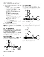
C. Trim insulation back 1/2” (13mm) from supply
wire and motor lead ends (Figure 4-2).
D. Insert motor lead ends and supply wire ends
into butt connectors. Match wire colors between
supply wires and motor leads.
E. Using crimping pliers, indent butt connector lugs
to attach wires (Figure 4-3).
F. Cut Scotchfil
™
electrical insulation putty into
3 equal parts and form tightly around butt
connectors. Be sure Scotchfil overlaps insulated
part of wire.
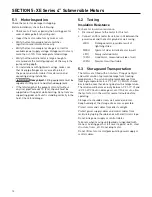
G. Using #33 Scotch
®
tape, wrap each joint tightly;
cover wire for about 1-1/2” (38mm) on each side
of joint. Make four passes with the tape. When
finished you should have four layers of tape tightly
wrapped around the wire. Press edges of tape
firmly down against the wire (Figure 4-4).
NOTICE: Since tightly wound tape is the only means
of keeping water out of splice, efficiency of splice will
depend on care used in wrapping tape.
NOTICE: For wire sizes larger than No. 8 (7mm
2
), use
soldered joint rather than Scotchfil putty, Figure 4-5.
Electrical Power
SECTION 4: Electrical Power
Figure 4-1: Mixing Wire Sizes: Example
Cable
Pump
Controls
Service Entrance
(Main Fuse Box
From Meter)
5 HP (4.9 kw)
230V 1Ph Motor
160 Ft. AWG 8
370 Ft.
5401 0412
Figure 4-2: Insert Wires
1/2"
(12.7mm)
Butt Connector
Figure 4-4: Wrap Splices
Completed splice
5186 1105
Alternate method
twist and solder
5187 1105
Figure 4-5: Twist Wires
Indent here
5185 1105
Figure 4-3: Indent Connectors
Scotchfil
™
is a trademark of 3M Company.
Scotch is a registered trademark of 3M Company.
Содержание P42B0007A2-01
Страница 1: ...pentek Electronics Manual Installation Operation Maintenance WWW PUMPS COM ...
Страница 108: ...NOTES ...
Страница 109: ...NOTES ...


