background image

Figure 10: Sn-2 Sensor Type Selection screen

Note: 

If your control system does not use

three sensors, simply press 

Next

 while the two

dashes are flashing in a Sensor Type Selection

screen to save no Sensor Type and go to the

next screen.

4.

In the 

Sn-3 Sensor Type Selection

 screen, press 

Up

or 

Down

 to select the desired Sensor Type (°F, °C, rH,

or --). Press 

Next

 to save your selection and go to the

Temperature Offset Setup screen for Sn-1.

The following figure shows Sn-3 set to rH.

Figure 11: Sn-3 Sensor Type Selection screen

5.

Press 

Up

 or 

Down

 to select a temperature offset

value. Press 

Next

 and either:

- go to the next 

Temperature Offset Selection

screen (if there are additional temperature

sensors in your control system) and repeat

this step for each temperature sensor.

- return to the 

Sensor Setup Start

 screen.

The following figure shows 0 as the selected

temperature display offset value for Sensor 2.

Figure 12: Temperature Display Offset Selection

screen

Select a temperature offset for each tempera-

ture (only) sensor in your control system. The

selected offset value is added to the sensed

temperature value to calculate the displayed

temperature value (sensed °F + OFFS = dis-

played °F). The Temperature Display Offset

value is typically 0 or a very low value.

Sensor Type 

°F

 enables an offset of +/- 5°F in 1

degree increments. Sensor Type 

°C

 enables an

offset of +/- 2.5°C in 0.5 degree increments.

6.

Press 

M

 to scroll through the remaining Setup Start

screens and continue setting up your control system,

or press 

Up

 and 

Down

 simultaneously to return to

the System 450 Main screens. The hardwire sensors

are setup in the UI.

Figure 13: Sensor Setup Start screen

Setting up the System 450 Reset
Setpoint

The System 450 Reset Control Modules feature

temperature and humidity setpoint reset capability based

on a Master temperature sensor (Sn-1) and a control loop

sensor (Sn-2).

You easily can set up a custom calculated (floating)

Reset Setpoint (RSP) that can be referenced by any of

the outputs in your control system. All control system

outputs that are set up to reference the Reset Setpoint

sensor (rES) use the same RSP setup parameters and RSP

to control output. During normal operation the current

RSP is displayed in one of the Main screens.

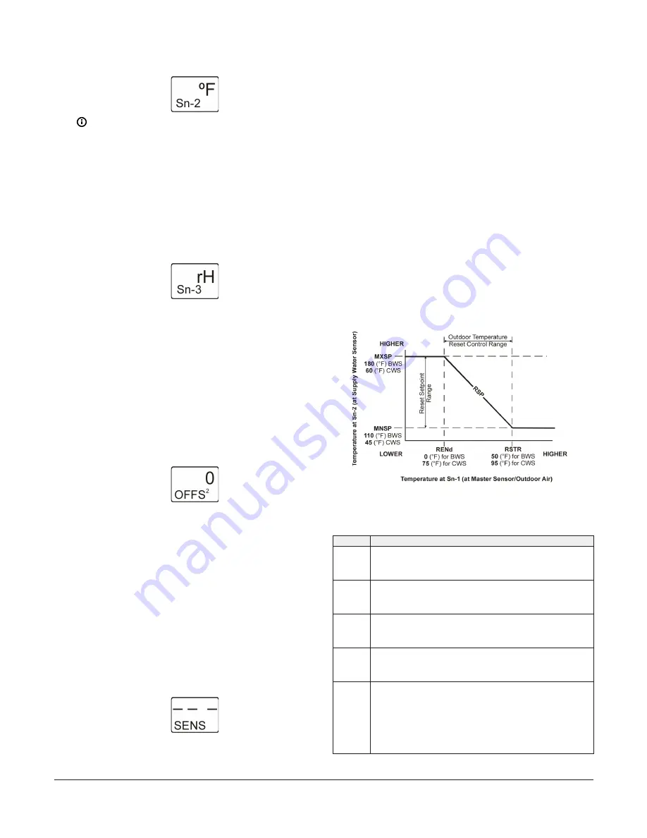
The following figure and table illustrate the relationships

between the setup parameters that define the calculated

RSP.

Figure 14: Example Reset Setpoint Applications for

Boiler Water Supply and Chiller Water Supply showing

the relationships between the Reset Setpoint Setup

parameters

Table 4: Example Reset Setpoint Applications for Boiler

Water Supply and Chiller Water Supply details

Item

Description

MNSP

Minimum Reset Setpoint
(110 [°F] BWS Temperature)
(45 [°F] CWS Temperature)

MXSP

Maximum Reset Setpoint
(180 [°F] BWS Temperature)
(60 [°F] CWS Temperature)

RSTR

Reset Range Start Temperature
(50 [°F] Outdoor Air for BWS)
(95 [°F] Outdoor Air for CWS)

RENd

Reset Range End Temperature
(0 [°F] Outdoor Air for BWS)
(75 [°F] Outdoor Air for CWS)

RSP

Calculated (Floating) Reset Setpoint
From 0 to 50°F outdoor air, the Boiler Water Supply (BWS) setpoint is reset
between 180 and 110°F. Above 50°F outdoor air, the BWS setpoint is 110°F.
Below 0°F outdoor air, the BWS is 180°F.
From 75 to 95°F outdoor air, the Chiller Water Supply (CWS) setpoint is
reset between 60 and 45°F. Above 95°F outdoor air, the CWS setpoint is
45°F. Below 75°F outdoor air, the CWS is 60°F.

System 450 Series Reset Control Modules with Real-Time Clock and Relay Output Installation Guide

9

Содержание System 450 C450RBN-1

Страница 1: ...ith reset control and or real time setback control for temperature and humidity only control applications System 450 expansion modules allow you to control up to 10 outputs which can be relay and anal...

Страница 2: ...lies before mak ing electrical connections More than one disconnec tion or isolation may be required to completely de en ergize equipment Contact with components carrying hazardous voltage can cause e...

Страница 3: ...and input sensor terminals low voltage less than 30V Labels 5V 24V Sn 1 Sn 2 Sn 3 Note Common terminals C are internally connected 2 6 pin module connector 3 Second output relay and terminal block La...

Страница 4: ...ion Module 16 Analog Output 4 Table 1 System 450 terminal wiring information Label Terminal function Wire sizes 24V Accepts 24 VAC supply power when a C450YNN power module is not connected and provide...

Страница 5: ...nd Down for 5 seconds to access the Setup Start screens 7 Menu button Press M to move through the sensor and output setup start screens When moving through the status or setup screens press M to retur...

Страница 6: ...s of the assembly outputs which requires setting up the outputs again See Figure 4 for an explanation of the System 450 display screen and the 4 button touch pad features and functions See Table 3 for...

Страница 7: ...s that the Analog Output is set up with SP EP and OSP OEP and Relay Output 2 has 17 hours of total runtime relay ON Figure 7 System Status screens Accessing the System 450 Setup screens 1 Apply power...

Страница 8: ...screens are view only selections cannot be made in Setup Start screens 2 In the Sn 1 Sensor Type Selection screen press Up or Down to select a Sensor Type F C or Press Next to save your selection and...

Страница 9: ...Setup Start screen Setting up the System 450 Reset Setpoint The System 450 Reset Control Modules feature temperature and humidity setpoint reset capability based on a Master temperature sensor Sn 1 an...

Страница 10: ...screen The remaining figures in this procedure show the setup parameter values selected for the RSP high and low temperature shutdown unoccupied setback and load balancing that are used by the output...

Страница 11: ...en The following figure shows an Shutdown High Temperature value of 65 F selected Figure 20 Shutdown High Temperature Selection screen 7 In the Shutdown Low Temperature Selection screen press Up or Do...

Страница 12: ...e the following sections Setting up a Relay Output with Reset Setpoint Setting up an Analog Output with Reset Setpoint Setting up a Standard Relay Output A standard relay output provides On Off contro...

Страница 13: ...mains off after reaching the OFFT value Minimum Relay OFF Time range is 0 to 300 seconds Press Next to save your selection and go to the next screen The following figure shows 10 seconds selected for...

Страница 14: ...et up in Setting up the System 450 Reset Setpoint Figure 35 Relay Output Setup Start screen 2 In the Sensor Selection screen press Up or Down to select the Reset Setpoint Sensor rES for the output to...

Страница 15: ...nge is 0 to 300 seconds Press Next to save your selection and go to the next screen The following figure shows 0 seconds selected for the minimum OFF Time for Output 2 Figure 40 Minimum Relay OFF Time...

Страница 16: ...gth at End Point OEP The LCD displays different Control Ramp icons for the four control actions The following figure shows an example of the analog output setup values and the resulting output signal...

Страница 17: ...e To set up a Standard Analog Output you must select Sn 1 Sn 2 or Sn 3 in this screen and the selected sensor must already be set up in the System 450 UI See Setting up System 450 Sensors for informat...

Страница 18: ...re limits to set point excursion The following figure shows 0 selected for the Unoccupied Setback value for Output 3 Figure 51 Unoccupied Setback Selection screen 8 In the Integration Constant Selecti...

Страница 19: ...sensor is not selected the remaining output setup screens do not appear If a sensor is already selected for the output the Sensor Selection screen does not appear here the next screen in the setup se...

Страница 20: ...tput When properly set up P I control can drive the load closer to Setpoint than proportional only control Press Next to save your selection and go to the next screen Initially you should select the I...

Страница 21: ...wing figure shows 12 hour clock format selected Figure 67 12 or 24 Hour Clock Selection screen 3 In the Time of Day Setup screen press Up or Down to set the current time Set the clock to real time Pre...

Страница 22: ...e unoccupied times The load balancing feature is not effected in its function as a result of Occupied Unoccupied modes See Figure 3 1 In the Occupied Unoccupied Schedule Setup Start screen press Next...

Страница 23: ...eriods for that day and the entire day is occupied and all outputs operate at their occupied setpoint value Occupied and Unoccupied time periods are available at 15 minute intervals only For example 1...

Страница 24: ...nd menu flow example System screens Description 1 Main screens Note The Main menu screens auto scroll during normal operation After two minutes of inactivity in any screen the display returns to the m...

Страница 25: ...eed 8 Standard analog output setup start screens Mixing valve output 9 Time and day clock setup start screens Note You can set Time and day and occupied or unoccupied schedule for any control system T...

Страница 26: ...VAC AC Full load Amperes 4 9 A AC Locked Rotor Amperes 29 4 A _____________________________________ 10 Amperes AC noninductive at 24 240 VAC Pilot Duty 125 VA at 24 240 VAC Clock accuracy 4 minutes pe...

Страница 27: ...or more of the following measures Reorient or relocate the receiving antenna Increase the separation between the equipment and receiver Connect the equipment into an outlet on a circuit different fro...

Страница 28: ...2020 Johnson Controls All rights reserved All specifications and other information shown were current as of document revision and are subject to change without notice www penncontrols com...

Отзывы: