background image

9.

In the 

Load Balancing Selection

 screen, press 

Up

or 

Down

 to enable (ON) or disable (OFF) the Load

Balancing feature for your Reset Control system.

When the System 450 Load Balancing feature is

enabled (ON), the control system uses the relay ON

time of each Relay Output that references the RSP

sensor and balances the total ON times of these

Relay Outputs by cycling ON the Relay Output with

the lowest total ON-time first, and the second lowest

ON-time second, and so on. Press 

Next

 to save

your selection and return to the Reset Setpoint Start

screen.

Note: 

The Load Balancing feature is not

available for analog outputs.
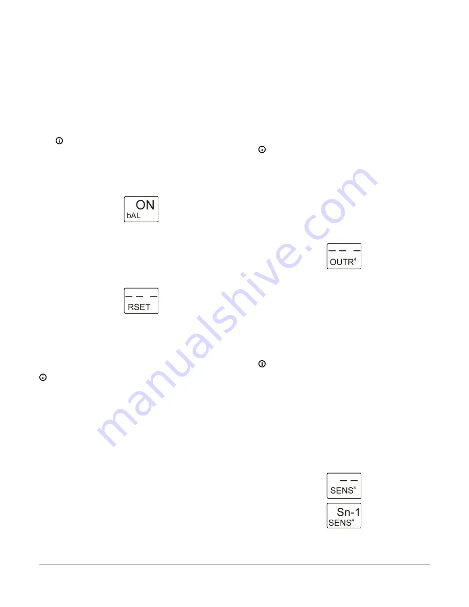
The following figure shows Load Balancing

feature is enabled (ON).

Figure 23: Load Balancing Selection screen

10. In the 

Reset Setpoint Setup Start

 screen, press 

M

 to

scroll through the remaining Setup Start screens and

continue setting up your control system, or press 

Up

and 

Down

 simultaneously to return to the System

450 Main screens. The Reset Setpoint is now set up in

the UI.

Figure 24: Reset Setpoint Setup Start screen

Setting up System 450 Outputs

After you build and connect power to your control system

module assembly, the output numbers and output types

for your control system are automatically assigned in the

UI.

Note: 

You must set up the system sensors for your

control system before you can set up the outputs.

1.

Access the System 450 setup screens. (See 

Accessing

the System 450 Setup screens

.) The 

Sensor Setup

Start

 screen appears.

2.

At the 

Sensor Setup Start

 screen, press 

M

repeatedly to scroll through and select the desired

Output Setup Start

 screen. The Output Setup Start

screen indicates the output number and the output

type for the selected output.

To set up Standard System 450 outputs without Reset

Setpoint, see the following sections:

Setting up a Standard Relay Output

Setting up a standard Analog Output

To set up System 450 outputs with Reset Setpoint, see the

following sections:

Setting up a Relay Output with Reset Setpoint

Setting up an Analog Output with Reset Setpoint

Setting up a Standard Relay Output

A standard relay output provides On/Off control for your

application based on a fixed setpoint sensor (Sn-1, Sn-2,

or Sn-3).

1.

In the 

Relay Output Setup Start

 screen, press

Next

 to go to the Sensor Selection screen. The

output number and output type (relay or analog) are

automatically assigned when you connect power to

the module assembly. See the Standard Relay Output

Setup Screens row in the setup screens flow chart in

System 450 menu flow example

.

Note: 

 All Setup Start screens are view-only;

selections cannot be made in Setup Start

screens.
The following figure shows the 

Relay Output

Setup Start

 screen for Output 4. The remaining

screens in this table show the parameter

values selected for controlling the boiler water

circulation pump connected to Relay Output 4

in Figure 3.

Figure 25: Relay Output Setup Start screen

2.

In the Sensor Selection screen, press 

Up

 or 

Down

 to

select the Sensor (Sn-1, Sn-2, or Sn-3) that the output

references. The sensor you select here determines

the output control type (standard or reset control),

and output’s setup parameters and value ranges.

Press 

Next

 to save your sensor selection and go

to the next screen. If a sensor is not selected, the

remaining output setup screens do not appear. If a

sensor is already selected for the output, the Sensor

Selection screen does not appear here and the next

screen in the setup sequence appears instead.

Note: 

To set up a Standard Relay Output, you

must select Sn-1, Sn-2, or Sn-3 in this screen,

and the selected sensor must already be set

up in the System 450 UI. See 

Setting up System

450 Sensors

 for information and procedures on

setting up sensors.
The following figure shows the initial Relay

Output 4 Sensor Selection screen with no

sensor selected, followed by the same screen

with the (Master) Sensor 1 selected for Relay

Output 4.

Figure 26: Sensor Selection screens

System 450 Series Reset Control Modules with Real-Time Clock and Relay Output Installation Guide

12

Содержание System 450 C450RBN-1

Страница 1: ...ith reset control and or real time setback control for temperature and humidity only control applications System 450 expansion modules allow you to control up to 10 outputs which can be relay and anal...

Страница 2: ...lies before mak ing electrical connections More than one disconnec tion or isolation may be required to completely de en ergize equipment Contact with components carrying hazardous voltage can cause e...

Страница 3: ...and input sensor terminals low voltage less than 30V Labels 5V 24V Sn 1 Sn 2 Sn 3 Note Common terminals C are internally connected 2 6 pin module connector 3 Second output relay and terminal block La...

Страница 4: ...ion Module 16 Analog Output 4 Table 1 System 450 terminal wiring information Label Terminal function Wire sizes 24V Accepts 24 VAC supply power when a C450YNN power module is not connected and provide...

Страница 5: ...nd Down for 5 seconds to access the Setup Start screens 7 Menu button Press M to move through the sensor and output setup start screens When moving through the status or setup screens press M to retur...

Страница 6: ...s of the assembly outputs which requires setting up the outputs again See Figure 4 for an explanation of the System 450 display screen and the 4 button touch pad features and functions See Table 3 for...

Страница 7: ...s that the Analog Output is set up with SP EP and OSP OEP and Relay Output 2 has 17 hours of total runtime relay ON Figure 7 System Status screens Accessing the System 450 Setup screens 1 Apply power...

Страница 8: ...screens are view only selections cannot be made in Setup Start screens 2 In the Sn 1 Sensor Type Selection screen press Up or Down to select a Sensor Type F C or Press Next to save your selection and...

Страница 9: ...Setup Start screen Setting up the System 450 Reset Setpoint The System 450 Reset Control Modules feature temperature and humidity setpoint reset capability based on a Master temperature sensor Sn 1 an...

Страница 10: ...screen The remaining figures in this procedure show the setup parameter values selected for the RSP high and low temperature shutdown unoccupied setback and load balancing that are used by the output...

Страница 11: ...en The following figure shows an Shutdown High Temperature value of 65 F selected Figure 20 Shutdown High Temperature Selection screen 7 In the Shutdown Low Temperature Selection screen press Up or Do...

Страница 12: ...e the following sections Setting up a Relay Output with Reset Setpoint Setting up an Analog Output with Reset Setpoint Setting up a Standard Relay Output A standard relay output provides On Off contro...

Страница 13: ...mains off after reaching the OFFT value Minimum Relay OFF Time range is 0 to 300 seconds Press Next to save your selection and go to the next screen The following figure shows 10 seconds selected for...

Страница 14: ...et up in Setting up the System 450 Reset Setpoint Figure 35 Relay Output Setup Start screen 2 In the Sensor Selection screen press Up or Down to select the Reset Setpoint Sensor rES for the output to...

Страница 15: ...nge is 0 to 300 seconds Press Next to save your selection and go to the next screen The following figure shows 0 seconds selected for the minimum OFF Time for Output 2 Figure 40 Minimum Relay OFF Time...

Страница 16: ...gth at End Point OEP The LCD displays different Control Ramp icons for the four control actions The following figure shows an example of the analog output setup values and the resulting output signal...

Страница 17: ...e To set up a Standard Analog Output you must select Sn 1 Sn 2 or Sn 3 in this screen and the selected sensor must already be set up in the System 450 UI See Setting up System 450 Sensors for informat...

Страница 18: ...re limits to set point excursion The following figure shows 0 selected for the Unoccupied Setback value for Output 3 Figure 51 Unoccupied Setback Selection screen 8 In the Integration Constant Selecti...

Страница 19: ...sensor is not selected the remaining output setup screens do not appear If a sensor is already selected for the output the Sensor Selection screen does not appear here the next screen in the setup se...

Страница 20: ...tput When properly set up P I control can drive the load closer to Setpoint than proportional only control Press Next to save your selection and go to the next screen Initially you should select the I...

Страница 21: ...wing figure shows 12 hour clock format selected Figure 67 12 or 24 Hour Clock Selection screen 3 In the Time of Day Setup screen press Up or Down to set the current time Set the clock to real time Pre...

Страница 22: ...e unoccupied times The load balancing feature is not effected in its function as a result of Occupied Unoccupied modes See Figure 3 1 In the Occupied Unoccupied Schedule Setup Start screen press Next...

Страница 23: ...eriods for that day and the entire day is occupied and all outputs operate at their occupied setpoint value Occupied and Unoccupied time periods are available at 15 minute intervals only For example 1...

Страница 24: ...nd menu flow example System screens Description 1 Main screens Note The Main menu screens auto scroll during normal operation After two minutes of inactivity in any screen the display returns to the m...

Страница 25: ...eed 8 Standard analog output setup start screens Mixing valve output 9 Time and day clock setup start screens Note You can set Time and day and occupied or unoccupied schedule for any control system T...

Страница 26: ...VAC AC Full load Amperes 4 9 A AC Locked Rotor Amperes 29 4 A _____________________________________ 10 Amperes AC noninductive at 24 240 VAC Pilot Duty 125 VA at 24 240 VAC Clock accuracy 4 minutes pe...

Страница 27: ...or more of the following measures Reorient or relocate the receiving antenna Increase the separation between the equipment and receiver Connect the equipment into an outlet on a circuit different fro...

Страница 28: ...2020 Johnson Controls All rights reserved All specifications and other information shown were current as of document revision and are subject to change without notice www penncontrols com...

Отзывы: