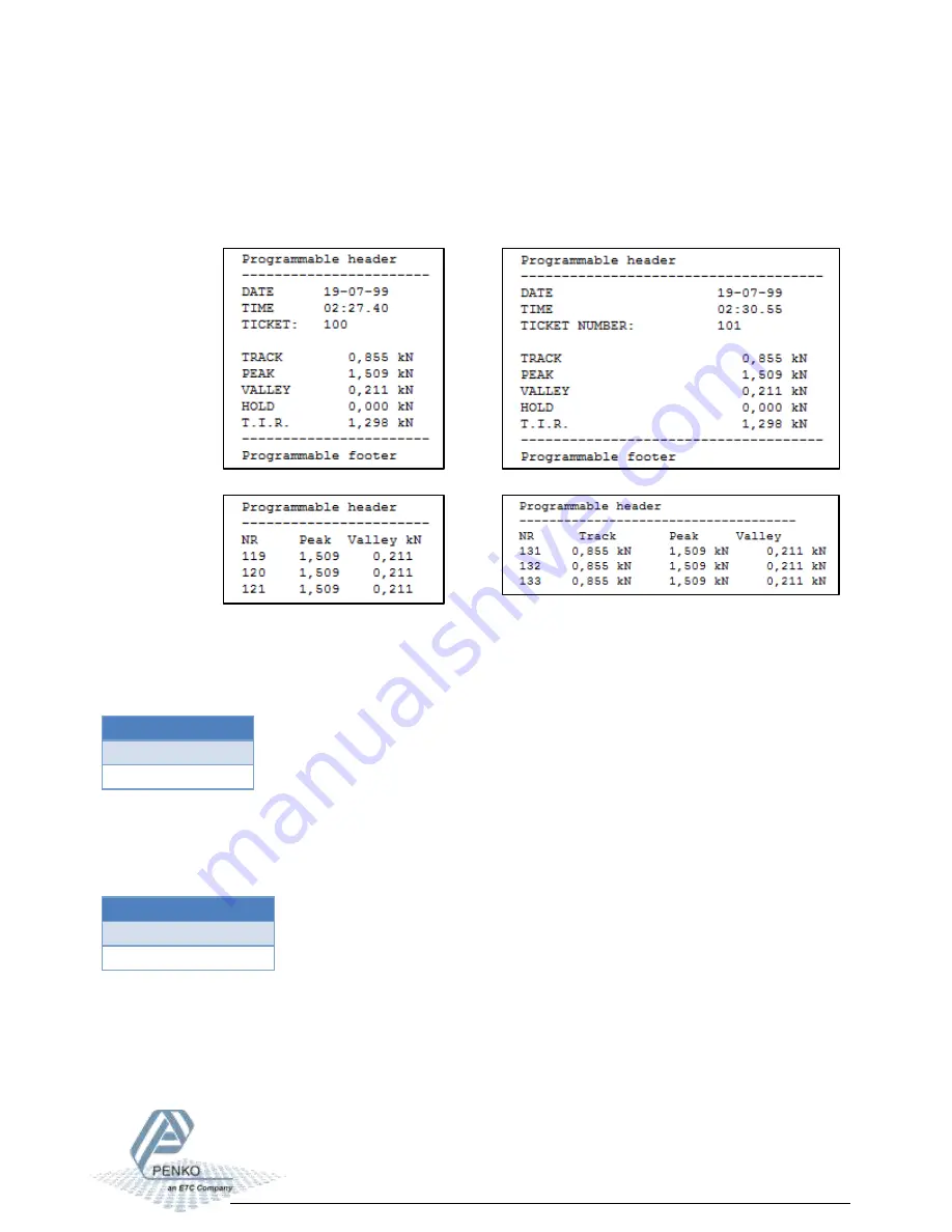
PENKO 1020 FMD Скачать руководство пользователя страница 81

1020 FMD 


81 


Layout 

Select the layout for printing. The 

Ticket

 layout is a predefined format. The 

Line

 layout prints 

every measurement on a new line. For both layouts a 24 and 40 columns format is present. 


24 columns 

40 columns 


Ticket 


Line 


Each print action has a number (ticket = ticket number, line = line number). When the device 
powers up the print counter is set to zero. 

Available options


Ticket 
Line 
 

Columns 

24 and 40 columns printing is supported as shown in the layout examples.  

Available options


0…39 = 24 columns 
40…80 = 40 columns 


Содержание 1020 FMD

Страница 1: ...1020 FMD 1 PENKO Engineering B V Your Partner for Fully Engineered Factory Solutions Manual 1020 FMD...

Страница 2: ...and these instructions contact your PENKO representative for clarification Pay careful attention to all warnings cautions and instructions marked on and supplied with the product Inform and educate yo...

Страница 3: ...cable conduit entries must be securely sealed by non flammable blanking plates or blind grommets to ensure complete enclosure integrity in compliance with personal safety and environmental protection...

Страница 4: ...2 5 Digital inputs 13 2 6 Digital outputs 14 2 7 Ethernet 15 2 9 CAN Bus 16 2 10 Profibus 17 2 11 RS232 RS422 18 3 Display and keypad 20 4 PC applications 24 4 1 PDI Client 24 4 2 Pi Mach II 25 5 Firs...

Страница 5: ...tory recall 84 6 4 Control 85 6 5 Access 85 7 Alibi Memory and Event Log 86 7 1 Alibi Memory 86 7 2 Event Log 91 8 Firmware update 95 8 1 Ethernet 95 8 2 USB 96 9 Backup and restore 98 9 1 Backup 98 9...

Страница 6: ...g purpose 2 x clip for mounting purpose 1 x connector for load cell connection 1 x quick start manual Needed for use To use the 1020 FMD the following items are needed Class 2 or Limited Power Source...

Страница 7: ...1020 FMD 7 1 Overview Option 1 Option 2...

Страница 8: ...e Serial CAN bus Profibus 4 Ethernet connection 5 USB connection 6 Digital inputs 3 7 Digital outputs 4 8 24VDC power supply 9 OPTION Analog output 10 Load cell connection 11 RS232 RS422 connection 12...

Страница 9: ...er describes the connections of the 1020 FMD Before connecting the device to a computer using USB make sure the USB driver is installed 2 1 Power supply Power the device using a Class 2 or Limited Pow...

Страница 10: ...ive Excitation voltage 5 VDC Sensitivity 0 1 V d Selectable ranges 1 mV V 1 5 mV V 2 mV V 2 5 mV V 3 mV V Input voltage 3mV V 16 mV to 16 mV A D Conversion speed 1600 s Max load cell impedance 1200 Mi...

Страница 11: ...e connecting the device to a computer using USB make sure the USB driver is installed The driver is included in the PENKO configuration PC applications see chapter PC applications Only 1 protocol is s...

Страница 12: ...20 mA The minimum and maximum output of the analog output 0 24 mA The minimum and maximum output of the analog output 4 20 mA The minimum and maximum output of the analog output 4 24 mA The minimum an...

Страница 13: ...1020 FMD 13 2 5 Digital inputs The device has 3 digital The inputs can be switched PNP or NPN with 18 28 VDC The inputs can be programmed as Hold Peak Hold Key Lock etc...

Страница 14: ...al outputs The device has 4 digital outputs that can be used for an AC and DC power circuit up to 35V 0 5A The outputs can be programmed as setpoints with a programmable hysteresis and function like T...

Страница 15: ...NKO FLEX controller EthernetIP Protocol to connect to SCADA PLC Omron FINS Protocol to connect to SCADA PLC Modbus TCP Protocol to connect to SCADA PLC Penko TP PENKO protocol used for configuration s...

Страница 16: ...s The CAN Bus can be used for the PENKO BusLink protocol a protocol to connect the 1020 FMD to a PENKO FLEX controller Connection Description H CAN High RTN Ground L CAN Low SH Shield The CANopen prot...

Страница 17: ...n No Symbol Name Description 1 SHIELD Shield protective ground 2 RP Reserved for power 3 B B RxD TxD P Receive Transmit data P 4 CNTR P Control P 5 C C DGND Data ground 6 VP Voltage plus 7 RP Reserver...

Страница 18: ...for the following protocols Protocol Description Printer PENKO protocol to connect a ASCII plain text printer ASCII PENKO protocol for ASCII communication NPV Slave PENKO Protocol used for follow disp...

Страница 19: ...1020 FMD 19 RS232 communication RS422 communication with multiple devices...

Страница 20: ...own on the display Tracking Hold T I R Peak Valley Display value Tracking Tracking value The display follows the input signal Hold Hold value The hold value is stored every time the zero button is pre...

Страница 21: ...1020 FMD 21 Hold function Peak Valley and T I R function...

Страница 22: ...CAL code TAC stands for Traceable Access Code A number of settings are only available after entering this code When these settings are changed the TAC is incremented with 1 CAL stands for CALibration...

Страница 23: ...o set tare zero Press again to reset tare zero In Hold mode press to set hold value In Peak Valley T I R mode press to clear the stored value Print Escape Press to cancel or step back one menu item Pr...

Страница 24: ...s used to explain the 1020 FMD functionality www penko com software 4 1 PDI Client PDI client is a small cross platform application that only works with USB communication It can run on any operating s...

Страница 25: ...tion and has more functionality compared to PDI Client The tree structure configuration of PDI Client is available in this program Other features are backup and restore firmware updates and a build in...

Страница 26: ...ication This chapter describes how to adjust these settings with the configuration software and on the device itself 5 1 Using the configuration software Make sure Pi Mach II and the USB driver are in...

Страница 27: ...e properties of the selected item in the left screen For example the live force information In the tree select PENKO 1020 The properties of this tree node are shown in the right screen The first use s...

Страница 28: ...position of the decimal point This setting will be used everywhere the measured force is displayed or printed Available options 000000 00000 0 0000 00 000 000 00 0000 0 00000 Step Select the step siz...

Страница 29: ...ayed value 1 2005 2 2006 5 2005 10 2010 20 2000 50 2000 100 2000 200 2000 Maxload Set the force the indicator will use as maximum If the measured force is higher than the maximum load the display will...

Страница 30: ...igurations don t affect the settings made in step 1 They only affect the filter settings Available options Unknown Standard indicator Fast indicator When setting up an installation select the appropri...

Страница 31: ...he voltage generated by the connected load cell or force sensor Scale empty The calibration of the zero point Make sure the load cell or force sensor is not loaded and is stable Click and the zero poi...

Страница 32: ...n to the device to access the device in the Ethernet network by name instead of by IP address Address Set the IP address of the device Make sure the IP address is in the IP range of the network Mask S...

Страница 33: ...ice parameters like indicator values and I O status become available in the PENKO FLEX A BusLink network can contain up to 40 PENKO devices 8 addresses x 5 sub addresses Address Set the BusLink addres...

Страница 34: ...ribed only once Protocol Select the protocol for the serial port Available options None Printer ASCII NPV Slave MODBUS RTU MODBUS ASCII Address Set the address of the port for identification in the ne...

Страница 35: ...Mark Space Baudrate Set the baud rate needed for the selected protocol Available options 1200 2400 4800 9600 19200 38400 57600 115200 Indicator This option is only active when ASCII is selected as pr...

Страница 36: ...ters like indicator values and I O status become available in the PENKO FLEX A BusLink network can contain up to 40 PENKO devices 8 addresses x 5 sub addresses Protocol Enable or disable the BusLink p...

Страница 37: ...Subaddress Set the BusLink sub address Available options 1 2 3 4 5 Baudrate Set the baud rate equal to the baud rate of the connected PENKO FLEX Available options 100k 125k 250k 500k The CANopen proto...

Страница 38: ...ress Set the Profibus address for the device Range 0 255 Format Set the format for the values sent over Profibus Available options Integer Floating point Select Done and click End Quick setup This wil...

Страница 39: ...along with all other settings Main Menu From the main screen press the Enter button for 2 seconds to enter the Main Menu Press 2 seconds Navigate through menu Use the Up and Down button to navigate t...

Страница 40: ...clear the whole value Select previous digit Select next digit Increase selected digit Decrease selected digit Confirm whole value Clear whole value Edit a text In case a text has to be edited a keybo...

Страница 41: ...1020 FMD 41 Change character set Indicator parameters The indicator parameters from the quick setup can be set as follows...

Страница 42: ...ttom corner of the screen using the arrow buttons apply with the Enter button Here the Unit Step size Decimal point and Max load can be set The predefined settings of step 2 in the quick setup are not...

Страница 43: ...20 FMD 43 Calibration The calibration from the quick setup can be performed as follows Enter the CAL as shown on the right bottom corner of the screen using the arrow buttons apply with the Enter butt...

Страница 44: ...D 44 Make sure the load cell or force sensor is not loaded and is stable before pressing Enter Make sure the load cell or force sensor is loaded with the reference weight and is stable before pressing...

Страница 45: ...1020 FMD 45 Enter the reference weight apply with the Enter button The device is now calibrated...

Страница 46: ...gs are also available in the device menu A full menu structure can be found in the attachment In the tree select PENKO 1020 The properties of this tree node are shown in the right screen The full sett...

Страница 47: ...F 1 ON Digital outputs Live status of the 4 digital outputs 0 OFF 1 ON Analog output Live output percentage of the analog output Counters Live counter status of the 3 digital inputs 6 2 System System...

Страница 48: ...uration 6 3 1 Service Service is for PENKO employees only 6 3 2 Indicator Indicator contains the indicator parameters and calibration PARAMETERS To enter the parameters enter the shown TAC and confirm...

Страница 49: ...the device in a multiple device setup optional Maxload Set the force the indicator will use as maximum If the measured force is higher than the maximum load the display will show Sample rate Select t...

Страница 50: ...size Available options Available options 1 2 5 10 20 50 100 200 Example Measured value is 2005 kN Step size Displayed value 1 2005 2 2006 5 2005 10 2010 20 2000 50 2000 Decimal point Select the positi...

Страница 51: ...s to be within the range of 0 002kN over the time of 1 00 second to indicate stable When stable the stable indication on the display will light up Zero tracking Zero tracking is able to tune the zero...

Страница 52: ...e is set to 0 MaxStep Select the biggest allowed step size Available options Step 1 Step 2 Step 5 Step 10 Step 20 Step 50 Step 100 Step 200 Mode Select the mode In multi range mode the step size is re...

Страница 53: ...ge number is indicated in the display In multi range mode the range will only get back to range 1 when the indicator has been lower or equal to zero In this case when the value goes down range 4 will...

Страница 54: ...ss of information or accuracy don t set the overall filter higher than 24dB When no accuracy is needed a higher filter setting is allowed to enable extreme filtering Filter type Select the type of fil...

Страница 55: ...5 Hz 5 0 Hz 10 Hz 20 Hz 40Hz Moving Average Set the moving average frequency for the selected filter Range 0 50 Display The display filter will damp the indicator signal to the display to get a calm...

Страница 56: ...s active Display Tracking Filter damping Select the strength of the filter 0dB is no filtering 48dB gives the strongest damping Available options 0 dB 6 dB 12 dB 18 dB 24 dB 30 dB 36 dB 42 dB 48 dB Di...

Страница 57: ...Apply button The parameters are now shown in the tree Force calibration Force calibration contains the calibration settings Display shows the current display values Tracking The current displayed tra...

Страница 58: ...oint calibration Add Replace point is used to add a calibration point When a point is added with a value that already exists the existing point will be replaced When a point is added with a new value...

Страница 59: ...oad is zero but it s possible to change the line position if there s weight on the scale To do so edit the actual weigh value to the new known value Transducers calibration Transducer calibration is u...

Страница 60: ...ioned on the datasheet Input range Input range is used to set the range for the connected load cell or force sensor Range Select the input range Available options Description 1mV V 1 5 mV V 2 mV V Cal...

Страница 61: ...the device to access the device in the Ethernet network by name instead of by IP address Address Set the IP address of the device Make sure the IP address is in the IP range of the network Mask Set t...

Страница 62: ...ice parameters like indicator values and I O status become available in the PENKO FLEX A BusLink network can contain up to 40 PENKO devices 8 addresses x 5 sub addresses Address Set the BusLink addres...

Страница 63: ...ribed only once Protocol Select the protocol for the serial port Available options None Printer ASCII NPV Slave MODBUS RTU MODBUS ASCII Address Set the address of the port for identification in the ne...

Страница 64: ...Mark Space Baudrate Set the baud rate needed for the selected protocol Available options 1200 2400 4800 9600 19200 38400 57600 115200 Indicator This option is only active when ASCII is selected as pr...

Страница 65: ...ters like indicator values and I O status become available in the PENKO FLEX A BusLink network can contain up to 40 PENKO devices 8 addresses x 5 sub addresses Protocol Enable or disable the BusLink p...

Страница 66: ...Subaddress Set the BusLink sub address Available options 1 2 3 4 5 Baudrate Set the baud rate equal to the baud rate of the connected PENKO FLEX Available options 100k 125k 250k 500k The CANopen proto...

Страница 67: ...1020 FMD 67 Profibus Address Set the Profibus address for the device Range 0 255 Format Set the format for the values sent over Profibus Available options Integer Floating point...

Страница 68: ...ero Zero Reset Reset indicator from zero Hold Store current value as hold value Peak Reset Reset the peak hold value Valley Reset Reset the valley hold value T I R Reset both peak and valley value Key...

Страница 69: ...1020 FMD 69 Action Hysteresis Set the hysteresis for each output The hysteresis can be positive or negative...

Страница 70: ...l for more accuracy Peak x10 Peak with extra decimal for more accuracy Valley x10 Valley with extra decimal for more accuracy Hold x10 Hold with extra decimal for more accuracy T I R x10 T I R with ex...

Страница 71: ...the DAC module is placed Manual Manual output level Set the percentage for the output when manual control is enabled Manual control Enable manual control of the output Manual 0 00 Set the output to 0...

Страница 72: ...difference between the peak hold and valley hold value Fast Tracking x10 Fast tracking with extra decimal for more accuracy Tracking x10 Tracking with extra decimal for more accuracy Peak x10 Peak wit...

Страница 73: ...t will send out 20 mA 100 6 3 7 Passwords The access to some menu items can be protected with a password This only applies when accessing the menu on the device itself With the configuration software...

Страница 74: ...r a menu item in the system setup menu The password screen appears enter the password to gain access to the menu item The menu item is now available when no actions are performed the access is blocked...

Страница 75: ...assigned to the Down button Available options Description None No function Zero Set Set indicator to zero Track Hold Toggle between tracking and hold display Track Show the tracking value on the disp...

Страница 76: ...Description Bar Dot Bar Peak Dot Peak Bar Reverse Dot Reverse Minimum Set the minimum value for the led bar Lower Margin Set a lower margin This setting works together with the Upper Margin setting U...

Страница 77: ...ue below the margin is yellow Value within the margin is green Value above the margin is red Maximum Set the maximum value for the led bar Step Set the value of the step size between the minimum and m...

Страница 78: ...only applies to the device The configuration software is always in English Available options English German French Dutch MenuTimer Set the time in seconds for auto escape menu This only applies to th...

Страница 79: ...een the peak hold and valley hold value Display x10 Default display with extra decimal for more accuracy Fast Tracking x10 Fast tracking with extra decimal for more accuracy Tracking x10 Tracking with...

Страница 80: ...dicated format to correct the device date An easy way to synchronize time and date is to use the Clock function in Pi Mach II 6 3 10 Printer A printer can be connected to the Ethernet or the serial po...

Страница 81: ...a 24 and 40 columns format is present 24 columns 40 columns Ticket Line Each print action has a number ticket ticket number line line number When the device powers up the print counter is set to zero...

Страница 82: ...nge 0 80 Newline Select the end of line sequence When Zebra ZPL II is selected a printer with this protocol can be used The Zebra printer commands are automatically added to the printer ticket Availab...

Страница 83: ...r ticket Up to 4 lines can be programmed Footer Footer 1 4 Optionally set a footer for the printer ticket Up to 4 lines can be programmed Ethernet printer IP number In case the selected printer port i...

Страница 84: ...ts after this action Backup A backup of the device configuration can be made within the device A password is required for the backup Contact PENKO for this password When using Pi Mach II manage to mak...

Страница 85: ...e Hold Reset Reset the stored hold value Peak Reset Reset the stored peak hold value Valley Reset Reset the stored valley hold value TIR Reset Reset the stored Total Indicated Readout value 6 5 Access...

Страница 86: ...nd print alibi records and event logs 7 1 Alibi Memory Alibi records are generated by a user action To generate records go to the Printer Settings menu and set Port to Alibi memory Every time the Prin...

Страница 87: ...the stored measurement of the data record Time Unit Time shows the time of the header record Unit shows the stored unit of the data record UID Every record has a Unique ID number the UID Print This wi...

Страница 88: ...1020 FMD 88 Example of a printer layout of these records The alibi records are also available on the device Press 2 seconds...

Страница 89: ...clear the alibi memory A confirmation screen is shown first Escape Print Leave the alibi memory Press for 2 seconds to print all records to a connected printer When a filter is active the filtered ra...

Страница 90: ...o set a date filter or type in a UID to filter on 1 specific record Leave the filter screen with the Escape button and the filter is applied When printing the alibi records only the filtered range is...

Страница 91: ...o see the event log go to the Access menu and select Event Log Number of entries The total number of event logs Entry Number Enter the number of the desired record and conform with Enter or the Apply...

Страница 92: ...s is explained further on Examples Number Record Tag Code Date Value Time Unit UID 1 Header SoftwareUpdate 31 0 14 09 11 28 3949592585 2 Header TAC Changed 06 08 14 14 18 48 1045692434 3 Header CAL Ch...

Страница 93: ...list on date or UID Select All to undo the filtering First Jump to the first entry of the list Escape Print Leave the event log Press for 2 seconds to print all records to a connected printer When a...

Страница 94: ...to set a date filter or type in a UID to filter on 1 specific record Leave the filter screen with the Escape button and the filter is applied When printing the event log only the filtered range is pri...

Страница 95: ...gh Ethernet Start PI Mach II Set communication to Ethernet Also see the Pi Mach II manual Start the Firmware Update Manager Click Open and select the PIP file Click Search for devices and select the d...

Страница 96: ...ct the 1020 FMD to the computer through USB Start PI Mach II Set communication to USB Also see the Pi Mach II manual Start the Firmware Update Manager Click Open and select the PIP file Click Search f...

Страница 97: ...1020 FMD 97 Now click Firmware Update to start the update The 1020 FMD will reboot automatically and the Firmware Update Manager will show Updated...

Страница 98: ...To back up the device open Pi Mach II Go to MENU ENVIRONMENT BACKUP DEVICE A save dialog is shown Choose a destination and filename and click SAVE The image will be created and saved to this destinati...

Страница 99: ...1020 FMD 99...

Страница 100: ...table condition Range 0 002 kN Time 1 00 s Zero tracking Range 0 000 kN Step 0 000 kN Time 0 00 s Range Interval Range 0 Parts Max Step 1 Mode Multi Range Filter Overall Overall Filter 0 dB Filter Dig...

Страница 101: ...KO 2111 Flash ROM exhausted Contact PENKO 2112 Error on header creation Contact PENKO 2113 Error on date write Contact PENKO 2114 Header validation failed Contact PENKO 2115 De active old data fail Co...

Страница 102: ...impedance 43 75 Max no of load cells 350 8 Max no of load cells 1 000 22 Max number of d 10 000 Display resolution 100 000 Internal resolution 24 bits Display steps 1 2 5 10 20 50 100 200 Display size...

Страница 103: ...1020 FMD 103...

Страница 104: ...log 97 Footer 86 Format Profibus 70 Function analog out 75 Function inputs 71 Function outputs 73 G Gateway 64 H Header 86 Hold 22 Hysteresis outputs 72 I Indicator on display 82 Indicator RS232 422 6...

Страница 105: ...able range 53 Stable time 53 Step Led bar 80 Step size 52 Stopbits RS232 422 66 Sub address Ethernet BusLink 65 System Setup password 76 T T I R 22 TAC 24 Tag Code alibi 90 Tag Code event 94 Time Unit...

Страница 106: ...1020 FMD 106 Appendix I Menu structure...

Страница 107: ...1020 FMD 107...

Страница 108: ...1020 FMD 108...

Страница 109: ...d from the website PENKO Printer Ethernet TCP RS232 422 PENKO printer protocol to connect ASCII plain text printers over Ethernet or serial connection Zebra ZPL II protocol is supported PENKO ASCII RS...

Страница 110: ...delines A library of testing certificates is available for reference on http penko com nl publications_certificates html PENKO Professional Services PENKO is committed to ensuring every system is inst...

Отзывы: