background image

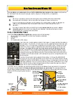
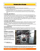
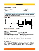
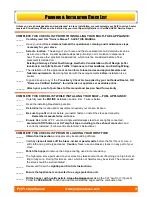
 12 

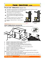
PELLET VENT TERMINATION:

  (Figures 7 & 8) 

Termination must be a minimum of 12‖ above the chase cap (B) (note: the chimney must meet 
local codes for height above the roof or other obstructions) 

Must have an approved cap (G) (to prevent water 
from entering) or a 45* elbow downturn (F) 


If the termination is located on a windy side of 
house, an approved house shield is recommended 
to prevent soot from accumulating on the side of the 
house. 

Must not be located where snow or other materials 
such as leafs, snow or grass, could block it. 

Must have a ―Metal Seal Plate‖  or ―Wall Thimble‖ at 
point (A) 


Figure 7 


Figure 8 


VENT TERMINATION CLEARANCES:


NOTE:   Horizontal terminations must protrude 12‖ from the wall, vertical terminations 24‖


A    Minimum 4’ clearance below or beside any door or window which opens. 
B    Minimum 1’ clearance above any door or window that opens. 
C     Minimum 3’ clearance from any adjacent building. 
D     Minimum 7’ clearance above any grade when adjacent to public walkways. 
E  

Minimum 2’ clearance above any grass, plants, or other combustible material. 


Minimum 1’ clearance above grade. 

F     Minimum 3’ clearance above any forced air intake of any other appliance within 6’. 
G    Minimum 2’ clearance below eves or overhang. 
H    Minimum 1’ clearance horizontally from combustible wall

I         Minimum 1’ clearance to inside corner 
X    Must be a minimum of 36‖ above the roof and 24‖ above the highest point of the roof within 10’. 


NOTE: 

The following are not found on the above diagram. 

Minimum 3’ above a gas meter/regulator within 3’ horizontally of the vertical centre line of regulator. 
Minimum 6’ clearance to a gas service regulator vent outlet. 
Minimum 1’ clearance under veranda, porch, deck or balcony.  Permitted only if structure is fully open on    
a minimum of two sides beneath the floor. 

A

B

A

B

3‘

10‘

2‘

x

Inside Corner

Detail

I

E

P

P

LANNING

LANNING


-

-


E

E

XHAUST

XHAUST


S

S

YSTEMS

YSTEMS


… 

… 

CONTINUED

CONTINUED


PelPro Appliances                       www.pelprostoves.com                                       12 

Содержание FPP Step Top Freestanding

Страница 1: ...to CAN CSA B365 Installation Code for Solid Fuel Burning Appliances and Equipment in Canada and NFPA 211 Chimney Fireplaces Vents and Solid Fuel Burning Appliances in the USA Contact local building or fire officials to obtain a permit and information on any installation requirements and installation inspection requirements in your area Rev A 01 2009 FPP Step Top Freestanding Rev B 09 2012 Toll Fre...

Страница 2: ...efficient satisfactory operation of your stove Initial Burn Setup of the stove is the most important step to ensure the efficient and satisfactory operation of your appliance for many years to come Pellet Stoves ARE NOT plug n play Know the quality and characteristics of the fuel you burn Corn Wheat or even Wood Pel lets can vary greatly from company to company from load to load and occasionally f...

Страница 3: ...RANTY 37 DETERMING SIZE DISTANCE 11 SERVICE MAINTENANE LOG 38 TERMINATION 12 PLANNING OUTSIDE AIR 13 APPLIANCE PLACEMENT 14 FLOOR PROTECTION CLEARANCES TO COMBUSTIBLES INSTALLATION TOOLS OF THE TRADE 16 STEP BY STEP DIRECT VENT INSTALLATION 17 INSTALLATION OPTIONS 18 MOBILE HOME NSTALLATION 20 OPERATION BEFORE LIGHTING YOUR FIRST FIRE 21 USING THE ACUTRON CONTROLS 22 CHOOSING YOUR MODE OF OPERATIO...

Страница 4: ...rranty and safety listing Keep foreign objects out of the hopper NEVER use gasoline gasoline type lantern fuel kerosene charcoal lighter fluid or similar liquids to start or freshen up a fire in this appliance Keep all such liquids well away from the appliance while it is in use This heater must be connected to a standard 115 V 60 Hz 3 prong grounded electrical outlet in accordance with local buil...

Страница 5: ... THE VENT SYSTEM MANUFACTURER S INSTRUCTIONS SEE LOCAL BUILDING CODE AND APPLIANCE AND VENT MANUFACTURER S INSTRUCTIONS FOR PRECAUTIONS REQUIRED FOR PASSING VENTING SYSTEM THROUGH A COMBUSTIBLE WALL OR CEILING UNDER CERTAIN CONDITIONS OF USE CREOSOTE BUILDUP MAY OCCUR RAPIDLY INSPECT AND CLEAN VENTING SYSTEM FREQUENTLY KEEP VIEWING ASH REMOVAL AND HOPPER DOORS TIGHTLY CLOSED DURING OPERATION REPLA...

Страница 6: ...ere Your stove s heat output can be adjusted from setting 1 4 through the FEED RATE touch pad to vary your heat output from Low to High The room air fan can be manually adjusted through the FAN SPEED to run faster or slower to correspond to the amount of heat being produced The room air fan is also on a limit switch controlled to run on high when the stove reaches higher temperatures and then resu...

Страница 7: ...itch installed If the temperature at the back of the firebox reaches approximately 250 F the switch will shut off the electricity going to the Vacuum Switch and to the Auger Motor The auger will automatically stop and the appliance will shut down when the exhaust temperature cools 120 F If this happens call your dealer or Hearth Home Technologies Customer Service 1 877 427 3316 IT IS IMPORTANT TO ...

Страница 8: ...sure that it is a Positive sign wave and a minimum 1000 watts continual EPA COMPLIANCE This heater is exempt from EPA Phase II requirements but has been tested for emissions using EPA test methods by Warnock Hersey US As listed by EPA under the name Hearth Home Technologies with an efficiency of over 77 and emissions of under 1 gram hour The unit is also certified with the State of Oregon D E Q an...

Страница 9: ...NCE _____ Carefully read the ENTIRE installation section first Twice is better _____ Read the Installing Freestanding section _____ Determine the location and measurement needed your chosen location _____ Be sure to pre fit all items before you install fasten or install the stove permanently Remember measure twice cut once _____ Ensure ALL joints of PL vent and single wall stainless steel liner ar...

Страница 10: ...must be installed at the bottom of all vertical runs These Tee s are to assist in periodically cleaning the vent Single or Double clean out tees may be used The exhaust system must be installed so the entire system can be cleaned without disassembly Termination must exhaust above the fresh air inlet elevation and parallel or above the exhaust output of the multi fuel appliance It is highly recomme...

Страница 11: ...ecessary to contact Hearth Home Technologies Customer Service personal to determine acceptable venting configurations and altitude adjustments 1 877 427 3316 The diagram to the right will help to give you a visual reference 0 1 2 3 4 5 6 7 8 9 10 10 20 30 Altitude in Thousands of Feet Equiva lent Pipe Length in Feet 3 or 4 Inch Diameter Pipe 4 Inch Diameter Only Use Diameter PL Vent If venting out...

Страница 12: ...learance from any adjacent building D Minimum 7 clearance above any grade when adjacent to public walkways E Minimum 2 clearance above any grass plants or other combustible material Minimum 1 clearance above grade F Minimum 3 clearance above any forced air intake of any other appliance within 6 G Minimum 2 clearance below eves or overhang H Minimum 1 clearance horizontally from combustible wall I ...

Страница 13: ...rmination When outside air is taken from an existing chimney the exhaust system must not terminate in the same chimney The outside air pipe on your stove is 2 OD The outside air connecting pipe must be at least 2 ID The outside air connecting pipe must be as short and free of elbows as possible and must fit over A not inside the outside air pipe on your stove For distances over 10 long 3 or 4 OD p...

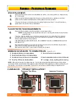
Страница 14: ...ibles 3 From PL Vent to Combustibles 2 From Front Side of Stove to Combustibles 2 From Back Corner of Stove to Combustibles 6 Non Combustible Surface In Front Of Heater 16 From Top Of Stove to Combustibles 36 to drapes doors anything that can swing Stove and floor protection must be installed on a level secure floor NOTE It is important for your appliance to be level Leveling should occur below th...

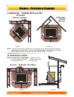
Страница 15: ...ve connect the Tee and measure off the 3 clearance ALCOVE INSTALLATION Minimum clearances to combustibles Figure 14 15 2 inch from back of appliance 6 inches from the sides 16 inches from the top 30 inches deep Figure 14 Figure 15 16 P PLANNING LANNING P PROTECTION ROTECTION C CLEARANCES LEARANCES 2 12 6 HROUGH HE ALL T T W ORNER 45 C 3 6 NTERIOR ERTICAL I V ORNER 45 C 6 6 6 6 6 1 10 6 2 12 LCOVE ...

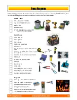
Страница 16: ...r and wire cutter Hammer Bubble Level Utility knife Adjustable pliers 6 to 8 inches Small hand broom and dustpan Furniture and Floor Protection Supplies Caulking tube of RTV Hi Heat Silicone Caulking tube of Clear Silicone Hi Heat Aluminum Foil Tape 2 long Wood screws 10 Assortment of sheet and wood screws Stove Bright Hi Heat Stove Paint Before starting your Pelpro Multi Fuel install we recommend...

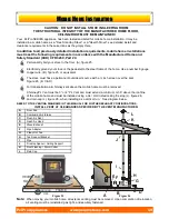
Страница 17: ...ad of RTV silicone around the end collar of the Quick Connect of your stove s exhaust C Firmly push the PL vent pipe adaptor J into the bead of RTV silicone Note If 4 PL vent is required use an 3 to 4 Pipe Adaptor Increaser J on the stove exhaust pipe 7 Connect the length of PL vent E that is in the thimble F onto the pipe adaptor D Fasten together with at least three sheet metal screws approx 3 8...

Страница 18: ...performance and provide natural draft to help evacuate smoke from the appliance in case of power 1 2 3 4 5 6 7 8 Main Floor Vertical 1 Pipe Adapter Clean Out Tee Cap 3 x 60 15 Pipe Length Tee Support Bracket Ceiling Support Firestop Spacer Roof Flashing Storm Collar Vertical Rain Cap 2 3 4 5 6 7 8 Tube of RTV Silicone Roll of Foil Tape 3 8 Stainless Self Tapping Screws x 27 2 Wood Screws x 10 8 16...

Страница 19: ... inlet Figure 26 B C D For transportation all chimney vent above the mobile home must be removed Chimney PL Vent must be 3 or 4 PL Vent and must extend a minimum or 36 above the roofline of the mobile home and must be installed using a UL ULC listed ceiling fire stop J figure 26 and rain cap L figure 26 when installing as a vertical run See diagram below REFER TO THE VENTING DIAGRAMS IN THIS MANUA...

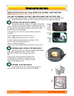
Страница 20: ...r pushed in all the way airflow is minimum Damper pulled out all the way airflow is increased To get the appliance started push the air damper in all the Way then pull outward approximately 1 2 This may not be the final setting We will cover FINE TUNNING YOUR STOVE later in this manual OPENING AND CLOSING THE MAIN DOOR Open the stove door by rotating the handle counter clock wise toward the top of...

Страница 21: ...tes your stove has heated to normal operating temperatures your stove will continue to run If the fire does not light and or burn properly the electricity to your stove s components will be shut off at the end of 15 minutes The FAN SPEED controls the speed of the room air fan This fan blows room air through the heat exchange tubes and back into the room When the FEED RATE is set to a higher positi...

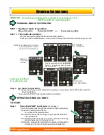
Страница 22: ...es 1 4 Only be concerned with the lights All others do not effect the mode selection process FEED RATE NOTE The Starting Point of the cycle depends on what mode the control was in Thermostat On Off Mode Thermostat Low High Mode Manual You are in control OPERATING IN MANUAL MODE TO START Step 1 Press the START touch pad It s that easy The control board goes through the entire start up automatically...

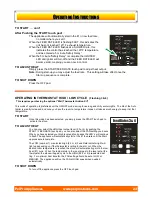
Страница 23: ...w heat 1 cycle When the temperature in the room drops to the level set at the thermostat the stove will again cycle to the HIGH 2 3 or 4 preselected set ting For optimum heat transfer the FAN setting should be set at LOW or MEDIUM The appliance will run the FAN at HIGH speed when needed automatically TO SHUT DOWN To turn off the appliance press the OFF touch pad TO START con t After Pushing the ST...

Страница 24: ...eat output over time eliminating the need for the thermostat to repeatedly turn the stove off Feed Rates 1 2 TRIM POTS Fine Tune Adjustments Factory Settings FUEL FEED rates at the Lowest number 1 and highest number 4 settings can be adjusted by adjusting the fine tune trim pots located on the control panel To raise fuel feed turn trim pot counter clockwise and to lower turn clockwise To assist in...

Страница 25: ...ng The AUGER CYCLE LED will go solid for 3 seconds indicating signal being sent to auger motor The IGNITER LED will light up solid and the 300 watt igniter will begin to operate 2 On a primed AUGER system pellets will begin to fall into the BURN GRATE and the AUTO SELF IGNITER will automatically ignite the pellets in approx 3 5 min Note If stoves fails to light within 15 minutes shut off the stove...

Страница 26: ...te to the 4 setting or High Allow the appliance to run on HIGH for 10 minutes before you begin to make fine adjustments AUGER CYCLE indicator should be lit ON for 3 seconds and OFF for 3 5 seconds Adjust the AIR INLET DAMPER This will have to be set as the factory can not send the units out with the damper pre set This is done to accommodate a wide range of installations elevations and fuel type a...

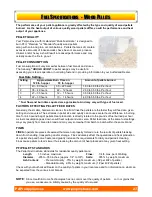
Страница 27: ... fuel settings may vary greatly from brand to brand and may vary somewhat from batch to batch within the same brand FINES FINES in pellets are pieces of sawdust that were not properly formed or are the results of pellets breaking down from handling transporting and or storage Fines adversely affect the operations and heat production of a pellet shop and home heater and greatly increase the require...

Страница 28: ...you do decide to carry it over make sure to check the corn for proper moisture content FACTORS EFFECTING FEED RATES Generally the smaller and cleaner free from fine dust and debris the corn is the faster it will feed at a given setting and visa versa The extremes in corn size moisture and quality can cause several hours difference in burning time for a hopper full of fuel Heat production is direct...

Страница 29: ...should be placed in a metal container with a tight fitting lid The closed container of ashes should be placed on a noncombustible floor or on the ground well away from all combustible materials pending final disposal If the ashes are disposed of by burial in Soil or otherwise locally dispersed they should be retained in the closed container until all cinders have thoroughly cooled WINDOW CLEANING ...

Страница 30: ... door may be removed to have frayed broken or compacted gaskets replaced EXHAUST VENTING Soot and Fly Ash Formation and Need for Removal The by products of com bustion contain small particles of fly ash Fly ash will collect in the exhaust venting system and restrict the flow of flue gases Incomplete combustion such as during startup shutdown or incorrect operation of the room heater will lead to s...

Страница 31: ...r a vinegar and water solution along with a rag Oven cleaner and window cleaners will leave a film on the glass that will attract smoke and creosote like a magnet Should a build up of creosote or carbon accumulate you may wish to use 000 steel wool and water to clean glass Ceramic is very hard and will not scratch from the steel wool GLASS REPLACEMENT In the event you need replacement only Hi Temp...

Страница 32: ...er Ensure the stove is plugged in to a 120VAC electrical outlet and a Surge Protection unit Check outlet for electrical power and proper voltage Check spade connections from the stove power cord to the main wiring harness Ensure door is closed and securely latched Ensure ash pan is tightly secured 2 Control Board Confirm mode of operation see OPERATION section for details Confirm power to the boar...

Страница 33: ...sure air holes are free of debris or build up 3 Igniter is not glowing Remove burn grate close door and re start the appliance If the igniter does not glow red inside the tube it is defective Remove back panel and confirm wire connections and condition of wires If igniter is defective the stove can be started manually See manual lighting instructions 4 Air Inlet Damper setting if igniter is glowin...

Страница 34: ...ust System Hi Heat RTV silicone all joints even manufactured Ensure venting is gas tight Inspect exhaust fan and gasket area ensure a tight fit Proper maintenance and cleaning 2 Over Feeding Fuel over filling burn grate Check air inlet damper for proper setting Adjust feed rate to lower level The stove keeps going out 1 Fresh unburned fuel or powder like ash build up in the grate Check air inlet d...

Страница 35: ...e only KS5080 1260 Burn Grate Bottom Plate Insert KS5020 1040 Combustion Fan w gasket KS5020 1050 Convection Fan w gasket KS5040 1090 Control Board AcuTron 2 Door Assembly black Door Assembly brass trim KS5140 1440 Door Handle KS5050 1130 Firebrick KS5060 1160 Gasket Door KS5060 1150 Gasket Window KS5060 1200 Gasket Ash Pan KS5060 1190 Gasket Exhaust KS5070 1210 Glass Neo Ceramic KS5030 1060 Ignit...

Страница 36: ...THE PURCHASER ACCEPTS RESPON SIBILITY LEGAL OR OTHERWISE FOR THE INCIDENTAL OR CONSEQUENTIAL DAMAGE TO THE PROPERTY OR PERSONS RESULTING FROM THE USE OF THIS PRODUCT ANY WARRANTY IM PLIED BY LAW INCLUDING BUT NOT LIMITED TO IMPLIED WARRANTIES OF MERCHANT ABILITY OR FITNESS SHALL BE LIMITED TO ONE 1 YEAR FROM THE DATE OF ORIGINAL PUR CHASE WHETHER A CLAIM IS MADE AGAINST THE MANUFACTURER BASED ON T...

Отзывы: