4
INTEGRATING THE DOOR TO THE
WATER RESISTIVE BARRIER
A.
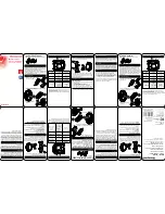
Apply side flashing tape.
Cut two pieces of flashing tape 4"
longer than the frame height of the door. Apply one piece 1/2"
onto the frame cladding, over the nailing fin and onto the water
resistive barrier on each side. The tape should extend 2" above the
top of the door and 2" below the bottom of the door. Press the
tape down firmly while folding down the excess tape at the top
and bottom of the door.
Interior
Exterior
Fixed Panel
Threshold
3H
3G
Architect Series and Designer Series
3
SETTING AND FASTENING THE DOOR (CONTINUED)
Exterior
4A
1"
4B
G.
Architect Series and Designer Series:
Apply sealant and insert a #8 x 2-1/2" pan head screw
(provided) into each hole in the bottom of the door frame (shown above in gold). Another
option is to use 3/16’ x 1-3/4” concrete screws. Drill pilot holes per manufacturers instructions.
Note: The flashing tape must be applied approximately 1/2" onto
the frame cladding at the jambs and head. Pre-folding the tape
at 1/2" before removing the paper backing will make it easier to
apply the tape correctly. If the siding is less than 1/2" thick, adjust
the dimension of the fold so the exterior sealant line will cover the
exterior edge of the tape.
B.
Apply top flashing tape.
Cut a piece of flashing tape long
enough to go across the top of the door and extend at least 1"
past the side flashing tape on both sides. Apply the tape 1/2"
onto the frame cladding, over the top nailing fin as shown. Fold
the overlapping tape down, and press all tape down firmly.
Note: The top flashing tape must overlap the side flashing tape
to prevent water from getting behind it.
H.
Architect Series and Designer Series:
Position and secure the panel retainer by drilling pilot
holes through the remaining holes in the retainer into the sill support or wood blocking, then
apply sealant to the holes and insert a screw into each hole as specified below.
Aluminum sill support:
9/64" pilot holes, #10 x 3/4" flat head thread cutting screws
(provided).
Wood
blocking:
1/8" pilot holes, #10 x 2-1/2" flat head wood screws (provided).
Masonry
floor:
3/16” x 1-3/4” concrete screw. Pilot drill per screw manufacturer’s
recommendations.
I.
Remove the factory installed screws
from the retainer and repeat the process.
J.
Architect Series and Designer Series:
Drill a
3/16" clearance hole at each indentation in the
extrusion at the top (head) of the door frame
into the rough opening, stopping when the drill
is through the door frame. Apply sealant to
each hole, then insert a #8 x 3" pan head screw
into each hole.
6HDODQW
JRHV
KHUH
´
3J


