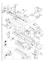


Indexing (27.27-1.27-2.27-3.27-4):
The index pin (27) allows you to make evenly
spaced inserts on a workpiece while locking the
main spindle. The spindle index indicator (20-5)
has 24 grooves. To use the index pin (27), screw it
into the mandrel until it fits into a hole in the
mandrel. Perform your first indexing operation.
Then unscrew the index pin so that it releases the
spindle and rotate to the next spindle position.
Continue until all functions are complete.
Always reset the index pin completely before
turning the lathe.
Center tracks (13):
The spur is locked into the head with a # 2 morse
code cone and holds the workpiece in place
while the spider is in operation. The percussion rod
slides into the spindle doll from behind to push out
the center spur. The percussion bar can be stored
in the hole on the front of the lathe. When
performing this operation, be sure to hold the
center spur to prevent it from falling out and
damaging the tip.
Warning - Be sure to clean both the cone on
the center spur and the inside of the
mandrel before mounting the center spur.
Failure to do so may result in the two
components differing and causing possible
damage to the tool.
Front plate (14):
Note! The front plate is pre-installed on your lathe.
Remove it before using the lathe. The front plate is
screwed directly onto the spindle dock. Use brass
screws (not supplied) to attach the workpiece to
the plate. Use screws that are not too long to
ensure that they do not get into parts of the
workpiece where you plan to remove the
material. To remove the plate from the spindle, lock
the spindle with the index screw and unscrew the
plate.
Tool support (31):
The tool support is used to support the cutting tool
while the turning is in operation. You can position
the tool support by releasing the locking handle
(34) on the side of the support and sliding the
rest into the desired position. Tighten the locking
handle to secure the tool in place. The height of
the tool support can be adjusted by loosening the
locking handle (35) on the front of the support and
adjusting the height to the desired position and
then tightening the locking handle. The position of
the entire tool can be adjusted by reaching under
the bed and loosening the clamping nut. Slide the
support into position, tighten the clamp nut. The
tool support should be placed just above the center
line of the workpiece.
Note! The locking handles are spring-loaded.
To use, pull out the lever, rotate it on the pin,
and then release.
Replacement of belt speeds:
Check that the lathe is disconnected. Loosen the
knob on the cover plate. Slide the cover up and
away from the lathe. Loosen the locking lever
on the motor plate (43) so that the motor plate
swings upwards. To change the speed, move the
pulley from one pulley to another. (Note: Always go
from the larger pulley to the smaller pulley). After
moving the belt, tighten the engine pulley with the
handle (43); this also stretches the strap. Turn
on the power switch and make sure the belt runs
consistently in its parallel groove (this should be
done with the handwheel (23)). If everything is
working, turn off the power and put the cover back.
Wiring diagram
Содержание 494213
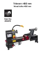
Страница 1: ...Tr svarv 450 mm Wood lathe 450 mm Item No 494213...
Страница 5: ......
Страница 8: ......
Страница 12: ......
Страница 15: ......
Страница 16: ...Verktygsboden Erfilux AB K llb cksrydsgatan 1 SE 507 42 Bor s Verktygsboden Bor s Sweden 0120504 03...


