


Special safety rules for wood lathe
WARNING: DO NOT USE YOUR WOOD LATHE
BEFORE IT IS FULLY ASSEMBLED AND INSTALLED
IN ACCORDANCE WITH THE INSTRUCTIONS.
1. For your own safety, read the whole
operating instructions before using the lathe.
2. Do not assemble a split workpiece.
3. Use the lowest speed when starting a new
workpiece.
4. Read the warning label attached the wood
lathe.
5. When turning a workpiece, always roughen the
wood to a round shape at slow speed. If the
lathe runs so fast that it vibrates, there is a risk
of the workpiece being thrown or the tool being
snatched from your hands.
6. Always rotate the workpiece manually before
turning on the engine. If the workpiece hits the
tool support, it can split and be thrown out of
the lathe.
7. Do not allow the turning tools to bite into the
wood. The wood can split or be thrown out of
the lathe.
8. Always place the tool at rest above the center
line of the lathe when shaping a workpiece.
9. Do not use the lathe if it rotates in the wrong
direction. The workpiece must always rotate
towards you.
10. Do not use the lathe if it rotates in the wrong
direction. The workpiece must always rotate
towards you.
11. Always place the tool at rest above the center
line of the lathe when shaping a workpiece.
12. Do not use the lathe if it rotates in the wrong
direction. The workpiece must always rotate
towards you.
13. Before attaching a workpiece the faceplate,
make it as round as possible. This minimizes
the vibrations while the piece rotates. Always
secure the workpiece securely to the faceplate.
Failure to do so may result in the workpiece
being thrown out of the lathe.
14. Position your hands so that they do not slip on
the workpiece.
15. Remove all loose hooks in the workpiece before
mounting it between the centers or on the front
plate.
16. Leave the work area only after the lathe’s motor
has stopped completely.
17. Hang your turning tools on the stand beyond
the rear end of the turning spindle. Do not place
them on the bench so that you have to extend
over the rotating workpiece to reach them.
18. Hold on and always keep control of the
turning tool. Take special precautions when
working on a part of the workpiece where pegs
or holes are located.
19. Make sure that the workpiece is stabile before
removing it from the lathe.
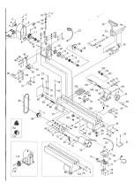
Adjustments
Assembly
Be sure to position the tool so that there is an
open space directly under the engine to protect the
chips from building up and soiling the engine fan
housing. For general work (portable) on table top,
mount the four rubber feet (50).
Tool stand (52):
Using the two screws (52-1), you can mount the
tool stand on the back of the lathe.
The stud (9,10,11,12):
Turn the stud’s handwheel (3) clockwise to extend
the stud doll spindle. Turn it counterclockwise to
retract it. The shaft (7) of the stud dock is locked
at its current extension. Be sure to release the lock
before attempting to adjust the spindle sleeve
extension. The handle (34) locks the back piece in
its current position on the stand next to the
mandrel. Detach to move the stud dock assembly
closer or farther from the spindle dock. To adjust
the clamp in the stand, slide the stud out of the
stand and turn the nut located on the bottom of the
stud.
Work lamp (28):
Use only a 40 watt or smaller light bulb in the work
light. Position the lamp to prevent chips from
accumulating in the lamp housing. Lamp not
included.
Power supply of the lathe:
The power switch (39-2) controls the power to the
motor. Switch the switch to the ON position and
the engine will start. The lathe begins to rotate
and reaches its full speed within a few seconds.
The time it takes for the motor to reach its full
speed depends on the size of the workpiece and
the speed setting. Switch the switch to the OFF
position to stop the lathe. Wait for the tool to come
to a complete stop before performing any further
operations.
The speed control knob (39-1) determines the
speed at which the lathe rotates. Turn the knob
clockwise to increase speed control and
counterclockwise to decrease speed. Always set it
to the lowest setting before turning the lathe. The
turning speed is digitally indicated by the monitor
(25).
Содержание 494213
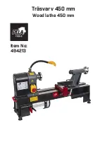
Страница 1: ...Tr svarv 450 mm Wood lathe 450 mm Item No 494213...
Страница 5: ......
Страница 8: ......
Страница 12: ......
Страница 15: ......
Страница 16: ...Verktygsboden Erfilux AB K llb cksrydsgatan 1 SE 507 42 Bor s Verktygsboden Bor s Sweden 0120504 03...


