


SECTION III
–
REASSEMBLY
3-1.
ROTATING ELEMENT.
(See Figure 1)
Reassemble as follows:
a. Coat the shaft (6) lightly with oil.
b. Place impeller key (32) in shaft keyway and one
impeller retaining ring (2A) in groove in shaft.
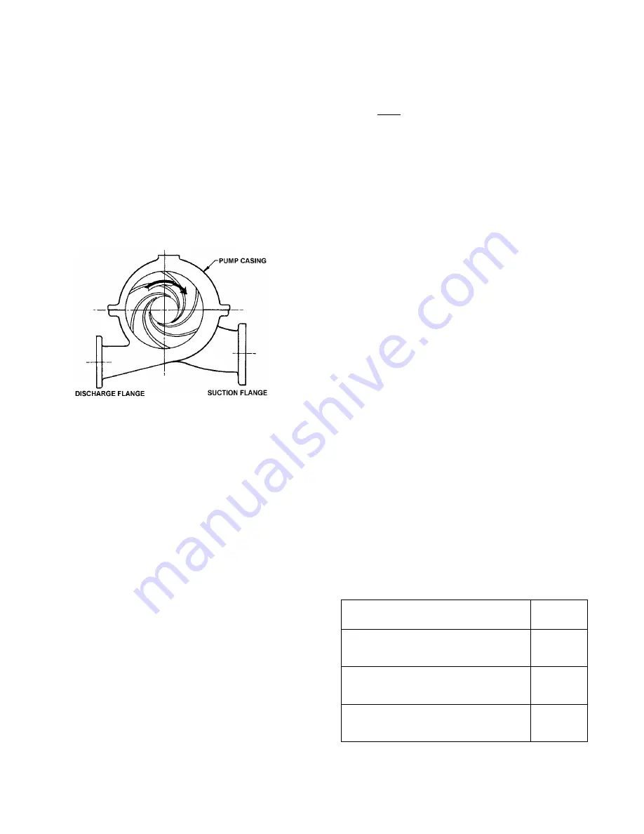
c. Align impeller (2) on shaft and install with an arbor
press or brass tubular sleeve and hammer until impeller
hub contacts the impeller retaining ring. Install the
second impeller retaining ring (2A). Guard against
bending shaft. When assembled, the impeller vanes
must rotate in the proper direction, (See Figure 3).
FIGURE 3. VANE POSITION FOR PROPER ROTATION
d. Locate casing rings (7) on impeller.
e. Lightly lubricate the O-rings on the O.D. of the
mechanical seal stationary elements (65), and install
stationary elements into glands (17). Install the gland O-
rings (119B). Place these assemblies over the shaft.
g. Slide bearings (16 &18) onto the shaft but do not
tighten bearing set screws at this time.
h. Install coupling key (46); and assemble coupling half
on the shaft and tighten the setscrews.
3-2.
PUMP.
Complete the assembly of pump as
follows:
a. Use factory supplied casing gasket (73A) or use the
upper casing (1B) as a template to cut a casing gasket
(73A) from 1/64 inch Vellumoid (SAE P3313B). It is very
important that specified material and thickness be used
for casing gasket. Machined surfaces of both casings
must be perfectly clean and free from burrs and nicks.
b. Affix the new casing gasket to lower casing (1A). Trim
the gasket carefully with a sharp knife. The casing
gasket must seal against the gland. O-ring (119B).
c. Se the rotating element into lower casing. Position the
casing rings (7) so that the dowel pins engage in slots in
the lower case split surface.
d. Center the shaft in the lower case so that the
dimension from the shaft shoulder at the mechanical
seal (80) to the end of the lower casing (1A) is the same
at each end of the pump.
e. Install and tighten the two cap screws attaching the
outboard bearing (18) to the lower case (1A).
f. Tighten the setscrews holding the inner race of the
outboard bearing (18) to the shaft (6). Replace the
protective cap which covers the outboard end of the
shaft.
g. Carefully locate the upper casing on the lower and
install the two dowel pins. Install and tighten the cap
screws working from the center of the casing to each
end. Tighten to the torque values in Table II. If any cap
screws require replacement, use only parts with equal or
greater tensile strength. Rotate shaft by hand to check
that it turns freely.
h. Replace all plugs removed during disassembly.
i. Lubricate the bearings.
NOTE
It is very important to provide proper lubrication and
to keep bearings clean. Frequency of lubrication must
be determined by experience, as it depends upon
bearing
size,
speed,
operating
conditions
and
environment. Table III should be used only as a guide for
re-lubrication.
TABLE III
GREASING FREQUENCY
SERVICE
GREASE
EACH
Normal, 8-hour day operation. Room
free of dust and damaging
atmosphere.
6 Months
Sever, 24-hour day operation. Room
with moderate dust and/or damaging
atmosphere, or outdoor service.
1 Month
Light, approximately 10-hour week.
Room relatively free of dust and
damaging atmosphere.
1 Year
5