background image

55 von 58

AUSGEGEBEN: 10-30-09  BLATT NR.: 095-9297-7  07-11-11

Deutsch

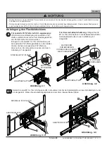
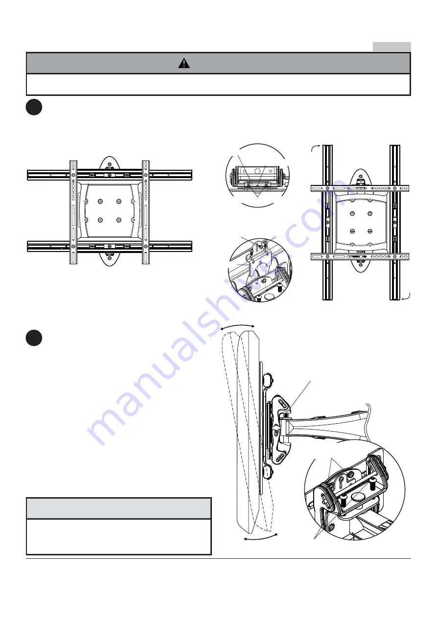
AUSRICHTEN DES BILDSCHIRMS IM HOCH- ODER QUERFORMAT: 

Entfernen Sie zwei M5 x 12mm 

Schrauben, M5 x 6mm Schrauben und den Drehblock von der Oberseite des Neigungskopfs wie in der Draufsicht 
und Rückansicht dargestellt. Fassen Sie den Bildschirm vorsichtig an den Seiten, drehen Sie ihn wie in Abbildung 
5.1 dargestellt in das Hoch-oder Querformat und bringen Sie den Drehblock mit zwei M5 x 12mm Schrauben 
wieder an und M5 x 6mm Schrauben. 

HINWEIS:

 Schraube M5 x 6mm notwendig im Querformat nur.

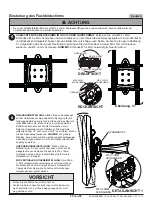
NEIGUNGSEINSTELLUNG:

 Stellen Sie den Spannknopf 

auf der Halterseite auf die gewünschte Spannung für die 
Neigungseinstellung sowie für die Größe und das Gewicht 
Ihres Bildschirms ein. Ziehen Sie an der Oberkante des 
Bildschirms bzw. drücken Sie die Unterkante, um die 
Neigung einzustellen (siehe Abbildung). Die maximale 
Neigung beträgt 10° nach vorne bzw. 5° nach hinten. Ziehen 
Sie den Spannknopf wieder an. 

HINWEIS:

 Für größere 

Displays, kann Spannschraube auf der gegenüberliegenden 
Seite des Berges müssen mit 5/32 Zoll Inbusschlüssel (

M

)

angezogen werden.

QUERNEIGUNGSEINSTELLUNG:

 Drehen Sie den 

Bildschirm um 5° nach rechts oder links, richten Sie ihn 
waagerecht aus und ziehen Sie dann die M5 x 10mm 
Schrauben mit dem 5mm Inbusschlüssel (

I

) fest wie in 

Detailansicht 1 darstellt.

ZUR VERTIKALEN HÖHENEINSTELLUNG:

 Um ±25mm 

(1 Zoll) vertikaler Höheneinstellung zu erzielen, müssen 
die beiden M8 x 40mm Schrauben wie in Detailansicht 
1 dargestellt um die gleiche Anzahl von Umdrehungen 
festgezogen bzw. gelöst werden.

Einstellung des Flachbildschirms

5

6

SPANNKNOPF

DETAILANSICHT 1

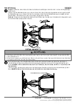
•   Ziehen Sie die Schrauben nicht zu fest an.
•   Achten Sie darauf, dass Sie die F inger nicht einklemmen, 

wenn der Halter von der Wand weg gezogen bzw. zu ihr 
hin geschoben wird.

VORSICHT

M5 X 12MM 

SCHRAUBEN

M5 X 6MM 

SCHRAUBEN

M5 X 10MM 
SCHRAUBEN

M8 X 40MM 
SCHRAUBEN

DRAUFSICHT

RÜCKANSICHT

• Wenn der 

Adapterplatte (

A

)

 nicht mit M10 x 15mm Schrauben (

E

) gesichert und arretiert wird, kann der Bildschirm bei 

versehentlichem Anstoßen vom Halter herabfallen.

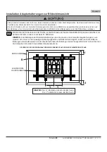
ACHTUNG

Abbildung. 5.1

DREHBLOCK

DREHBLOCK

VIS M5 X 6MM

M5 X 12MM SCHRAUBEN

Содержание 19306696

Страница 1: ...sembly Universal Articulating Arm Wall Mount for 32 to 52 Flat Panel Displays ISSUED 10 30 09 SHEET 095 9297 7 07 11 11 2300 White Oak Circle Aurora Il 60502 800 865 2112 Fax 800 359 6500 www peerlessmounts com Max UL Load Capacity 90 lb 41 82 kg ...

Страница 2: ...basic building construction and fully understands these instructions Make sure that the supporting surface will safely support the combined load of the equipment and all attached hardware and components Never exceed the Maximum Load Capacity See page one If mounting to wood wall studs make sure that mounting screws are anchored into the center of the studs Use of an edge to edge stud finder is high...

Страница 3: ...20 E M10 x 15 mm socket head screw 2 520 9262 F fastener caps 3 590 1324 G cable ties 8 590 1168 H 6 mm allen wrench 1 560 9716 I 5 mm allen wrench 1 560 9640 J rear cable cover 2 590 P1326 K front cable cover 2 590 P1327 L 3 screwdriver bit not shown 1 560 0209 M 5 32 allen wrench 1 560 9646 Parts List Parts may appear slightly different than illustrated Before you begin make sure all parts shown...

Страница 4: ...2mm 6 504 9013 M4 x 25mm 4 504 1015 M5 x 12mm 4 520 1027 M5 x 25mm 4 520 9543 M8 x 16mm 6 520 9257 M8 x 40mm 4 520 1136 M8 x 25mm 4 520 1031 I D 34 4 540 1059 I D 22 4 540 1057 M6 x 30mm 4 510 9109 M6 x 12mm 4 520 1128 M6 x 25mm 4 520 1208 M6 x 20mm 4 520 9402 multi washer 6 580 1036 ...

Страница 5: ...nting holes Installation to Single Wood Stud Wall 1 Installer must verify that the supporting surface will safely support the combined load of the equipment and all attached hardware and components Tighten wood screws so that wall plate is firmly attached but do not overtighten Overtightening can damage the screws greatly reducing their holding power Never tighten in excess of 80 in lb 9 N M Make s...

Страница 6: ...he block generally 1 25mm minimum from the side of the block Cinder block must meet ASTM C 90 specifications It is suggested that a standard electric drill on slow setting is used to drill the hole instead of a hammer drill to avoid breaking out the back of the hole when entering a void or cavity Concrete must be 2000 psi density minimum Lighter density concrete may not hold concrete anchor Make su...

Страница 7: ... 20 x 1 25 SCREWS 2 To prevent scratching the display set a cloth on a flat level surface that will support the weight of the display Place display face side down and refer to display manufacturers instructions for removing obstructions from the back of the display Adjust display brackets to align with display mounting holes Measure horizontal mounting hole pattern and choose fixed stop position fro...

Страница 8: ...ERTICALLY AND HORIZONTALLY ON BACK OF DISPLAY DISPLAY DISPLAY BRACKETS NOTE X dimensions should be equal Y dimensions should be equal Tighten screws so display brackets are firmly attached to display Do not tighten with excessive force Overtightening can cause stress damage to screws greatly reducing their holding power and possibly causing screw heads to become detached Tighten to 40 in lb 4 5 N M...

Страница 9: ...thread screw through multi washer display brackets B and spacer in that order into display as shown below Screw must make at least three full turns into the mounting hole and fit snug into place Do not over tighten If screw cannot make three full turns into the display select a shorter length screw from the baffled fastener pack Repeat for remaining mounting holes level display brackets and tighten ...

Страница 10: ...4 20 SELF TAPPING SCREWS 1 4 20 SELF TAPPING SCREWS Display BRACKETS Display BRACKETS INNER MOUNTING HOLES OUTER MOUNTING HOLES fig 3 1 fig 3 2 VESA 200 x 200 or VESA 200 x 100 Mounting Pattern To prevent scratching the display set a cloth on a flat level surface that will support the weight of the display Place display face side down and place universal adapter bracket B onto display 3 1 3 B B B 1 4...

Страница 11: ...play brackets into display as shown Screw must make at least three full turns into the mounting hole and fit snug into place Do not over tighten If screw cannot make three full turns into the display select a longer length screw from the baffled fastener pack Center display brackets vertically and tighten screws NOTE For displays with a bump out or recessed back spacer may be used Spacer goes betwee...

Страница 12: ...allen wrench H 4 1 A B B E ADAPTER PLATE ADAPTER PLATE DISPLAY NOT SHOWN FOR CLARITY Do not lift more weight than you can handle Use additional man power or mechanical lifting equipment to safely handle placement of the display Do not tighten screws with excessive force Overtightening can cause damage to mount Tighten M10 x 15mm screws E to 40 in lb 4 52 N M maximum torque WARNING Mounting Flat Pa...

Страница 13: ... tension knob NOTE For larger displays tension screw on opposite side of mount may need to be tightened using 5 32 allen wrench M Roll Adjustment Rotate display 5 clockwise or counter clockwise level display then tighten M5 x 10mm screws using 5mm allen wrench I as shown in detail 1 Vertical Height Adjustment Tighten or loosen two M8 x 40mm screws an equal number of turns to achieve 1 of vertical ...

Страница 14: ... Make sure cables have enough slack to allow full movement of the arm Run power cable through top or bottom of wall arm A and signal cable s through other side of arm in order to avoid interference with the signal Lock cables into place by snapping cable covers J K onto mount Display may have to be moved for easy access Optional If additional cable management is required route cable ties G through...

Страница 15: ...portes de pared de brazo articulador para pantallas planas de 32 a 52 PUBLICADO 10 30 09 HOJA 095 9297 7 07 11 11 2300 White Oak Circle Aurora Il 60502 800 865 2112 Fax 800 359 6500 www peerlessmounts com Máxima capacidad de carga para UL 90 lb 41 82 kg ...

Страница 16: ...los montantes Se recomienda utilizar un localizador de montantes de borde a borde Siempre cuente con la ayuda de un asistente o utilice un equipo mecánico de izar para levantar y colocar el equipo con más seguridad Apriete los tornillos con firmeza pero no en exceso Apretarlos en exceso puede dañar los artículos y puede disminu ir significativamente su fuerza de fijación Este producto está diseñado p...

Страница 17: ... 095 P1715 B soporte adaptador universal 1 095 P1635 2 C tornillos para madera 3 520 1202 D concreto de anclajes 3 590 0320 E tornillos de M10 x 15 mm 2 520 9262 F cubiertas para sujetadores 3 590 1324 G sujetacables 8 590 1168 H llave allen de 6 mm 1 560 9716 I llave allen de 5 mm 1 560 9640 J Cubierta trasera para cables 2 590 P1326 K Cubierta delantera para cables 2 590 P1327 Lista de piezas p ...

Страница 18: ...res arandela múltiple 6 580 1036 M4 x 12mm 6 504 9013 M4 x 25mm 4 504 1015 M5 x 12mm 4 520 1027 M5 x 25mm 4 520 9543 M8 x 16mm 6 520 9257 M8 x 40mm 4 520 1136 M8 x 25mm 4 520 1031 I D 34 4 540 1059 I D 22 4 540 1057 M6 x 30mm 4 510 9109 M6 x 12mm 4 520 1128 M6 x 25mm 4 520 1208 M6 x 20mm 4 520 9402 ...

Страница 19: ... para sujetadores F en los agujeros de montaje de la placa de pared Instalación en una pared con montante de madera único 1 7 54 192mm C F A CP fig 1 1 fig 1 2 El instalador debe verificar que la superficie de apoyo sea capaz de soportar firmemente la carga combinada del equipo y todos los herrajes y componentes Apriete los tornillos para madera de tal modo que la placa de apoyo quede firmemente sujeta ...

Страница 20: ...adro percutor para evitar romper la parte trasera del agujero al entrar en un espacio o cavidad El concreto debe tener una densidad mínima de 2000 psi Un concreto menos denso podría no ser capaz de sujetar el anclaje para concreto El instalador debe verificar que la superficie de apoyo sea capaz de soportar firmemente la carga combinada del equipo y todos los herrajes y componentes ADVERTENCIA Apriet...

Страница 21: ...NILLOS 1 4 20 x 1 25 2 Para evitar que se raye la pantalla coloque un trapo sobre una superficie plana y nivelada que sostenga el peso de la pantalla Coloque la pantalla boca abajo y se refieren a la pantalla las instrucciones del fabricante para eliminar las obstrucciones de la parte posterior de la pantalla Ajuste los soportes de la pantalla para alinear con los agujeros de montaje de pantalla Mid...

Страница 22: ...ón de los soportes adaptadores Apriete los tornillos de tal modo que los soportes adaptadores queden firmemente sujetos No apriete aplicando demasiada fuerza El apriete excesivo puede causar daño por esfuerzo a los tornillos reduciendo enormemente su fuerza de fijación y causando el posible desprendimiento de sus cabezas Apriete los tornillos a 40 pulg lb 4 5 N m de par torsor máximo Si los tornillo...

Страница 23: ... pantalla B y el espaciador en ese orden a la parte posterior de la pantalla como se muestra abajo El tornillo tiene que dar por lo menos tres vueltas completas dentro del agujero de montaje y debe quedar ajustado en su lugar No apriete los tornillos en exceso Si el tornillo no puede dar tres vueltas completas al entrar en la parte posterior de la pantalla seleccione un tornillo más largo de los s...

Страница 24: ...OPORTES DE LA PANTALLA SOPORTES DE LA PANTALLA SOPORTES DE LA PANTALLA AGUJEROS DE MONTAJE INTERIORES AGUJEROS DE MONTAJE EXTERIOR TORNILLO AUTORROSCANTE DE 1 4 20 VESA 200 x 200 o VESA 200 x 100 Patrón de montaje Para evitar que se raye la pantalla coloque un trapo sobre una superficie plana y nivelada que sostenga el peso de la pantalla Coloque la pantalla boca abajo y coloque el soporte adaptado...

Страница 25: ...entro del agujero de montaje y debe quedar ajustado en su lugar No apriete en exceso Si el tornillo no puede dar tres vueltas completas en la pantalla seleccione un tornillo más largo de la bolsa de tornillos ordenados Centralice los soportes de la pantalla verticalmente y apriete los tornillos NOTA Si la pantalla tiene la parte posterior abultada o empotrada puede utilizar el espaciador El espaci...

Страница 26: ...1 A B B E PLACA ADAPTADORA PLACA ADAPTADORA PLACA ADAPTADORA PLACA ADAPTADORA LA PANTALLA NO SE MUESTRA PARA QUE LA IMAGEN SEA MÁS CLARA Instalación de la pantalla plana 4 1 4 TORNILLOS DE M10 X 15MM 1 4 PLACA EXCLUSIVA PLACA EXCLUSIVA fig 4 1 fig 4 2 E fig 4 4 fig 4 3 Instalación del soporte adaptador universal Enganche los tornillos de M10 x 15mm en las ranuras de la placa adaptadora A como se muest...

Страница 27: ... hacia atrás Vuelva a apretar la perilla de tensión NOTA Para pantallas más grandes tornillo de tensión en el lado opuesto de montaje puede ser necesario apretarse con 5 32 llave allen M Ajuste de la ROTACIÓN Rote la pantalla 5 en el sentido de las manecillas del reloj o en el sentido contrario nivele la pantalla y luego apriete los tornillos de M5 x 10mm utilizando una llave allen de 5mm I como s...

Страница 28: ...os cables de la señal por el otro lado del brazo para evitar que haya interferencia con la señal Asegure los cordones en su lugar colocando las cubiertas de los cables J y K a presión sobre el soporte Es posible que necesite mover la pantalla para tener acceso OPCIONAL Si necesita acomodar más cables acomode los sujetacables G por las ranuras del brazo A como se muestra en el detalle 2 7 8 K J A G...

Страница 29: ...ants muraux pour écrans plats articulés pour écrans de 32 à 52 pouces PUBLIÉ LE 10 30 09 FEUILLE no 095 9297 7 07 11 11 2300 White Oak Circle Aurora Il 60502 800 865 2112 Fax 800 359 6500 www peerlessmounts com Capacité de charge UL maximale 90 lb 41 82 kg ...

Страница 30: ...r à montants en bois assurez vous que les vis de montage sont ancrées au centre des montants L utilisation d un localisateur de montants bord à bord est fortement recommandée Pour lever et positionner l équipement en toute sécurité faites vous toujours aider par une autre personne ou utilisez un dispositif de levage mécanique Serrez fermement les vis mais sans excès Un serrage excessif peut endomm...

Страница 31: ...Qté Pièce nº A bras mural 1 095 P1715 B adaptateurs universels 1 095 P1635 2 C vis à bois 3 520 1202 D concreto d ancrage 3 590 0320 E vis M10 x 15 mm 2 520 9262 F embouts de fixation 3 590 1324 G attaches de câble 8 590 1168 H hexagonale de 6 mm 1 560 9716 I hexagonale de 5 mm 1 560 9640 J Gaine de câble arrière 2 590 P1326 K Gaine de câble avant 2 590 P1327 L Tournevis à tête de 3 non illustré 1...

Страница 32: ...r M4 x 12mm 6 504 9013 M4 x 25mm 4 504 1015 M5 x 12mm 4 520 1027 M5 x 25mm 4 520 9543 M8 x 16mm 6 520 9257 M8 x 40mm 4 520 1136 M8 x 25mm 4 520 1031 I D 34 4 540 1059 I D 22 4 540 1057 M6 x 30mm 4 510 9109 M6 x 12mm 4 520 1128 M6 x 25mm 4 520 1208 M6 x 20mm 4 520 9402 rondelle universelle 6 580 1036 ...

Страница 33: ...les fixations Insérez trois embouts de fixation F dans les trous de fixation de la plaque murale 1 7 54 192mm C F A CE fig 1 1 fig 1 2 Installation sur un mur à montant en bois L installateur doit s assurer que la surface de support pourra soutenir sans danger la charge combinée de l équipement de toute sa visserie et de tous ses composants Serrez les vis à bois de manière que la plaque murale soit fer...

Страница 34: ...age bas au lieu d un marteau perforateur afin d éviter de briser la partie arrière du trou lorsque vous pénétrez un vide ou une cavité Le béton doit avoir une densité minimum de 2 000 psi Un béton de densité moindre risquerait de ne pas retenir un ancrage de béton Assurez vous que la surface de support pourra soutenir sans danger la charge combinée de l équipement de toute sa visserie et de tous se...

Страница 35: ...ayer l écran posez un morceau de tissu sur une surface plane et de niveau qui peut supporter le poids de l écran Déposez l écran à plat tourné vers le bas Consultez les instructions du fabricant de l écran avant d enlever tout bouton base couvercle ou vis situés à l arrière de l écran en préparation à l installation des supports d écran à l écran Réglez les supports de l écran de manière à les ali...

Страница 36: ... tous les trous soient bien alignés puis serrez les vis à l aide d un tournevis Phillips 2 2 Installation des Supports Adaptateurs à l écran N employez pas une force excessive pour serrer les vis Un serrage excessif peut endommager le support Serrez les vis à un couple maximum de 4 5 Nm 40 po lb Si les vis ne sont pas enfoncées de trois tours complets dans les inserts ou si elles sont serrées au m...

Страница 37: ...ellement à l écran en la faisant passer à travers la rondelle tout usage les supports de l écran B et l entretoise comme indiqué ci dessous La vis doit effectuer au moins trois tours complets dans le trou de fixation et tenir solidement en place Ne pas trop serrer S il est impossible d effectuer trois tours de vis complets choisissez une vis plus longue dans le jeu de fixations à compartiments Répét...

Страница 38: ...SE 1 4 20 VIS AUTOTARAUDEUSE 1 4 20 SUPPORTS D ÉCRAN TROUS DE FIXATION INTÉRIEURS TROUS DE FIXATION EXTÉRIEUR fig 3 1 fig 3 2 VESA 200 x 200 ou VESA 200 x 100 Modèle de montage Afin d éviter de rayer l écran posez un morceau de tissu sur une surface plane et de niveau qui peut supporter le poids de l écran Déposez l écran à plat tourné vers le bas et ensemble le support adaptateur universel B sur l é...

Страница 39: ... vis doit effectuer au moins trois tours complets dans le trou de fixation et tenir solidement en place Ne pas trop serrer S il est impossible d effectuer trois tours de vis complets choisissez une vis plus longue dans le jeu de fixations à compartiments Centrez les supports d écran à la verticale et serrez les vis REMARQUE Pour les écrans à dos convexes ou concaves des entretoises peuvent être util...

Страница 40: ...e 4 3 et 4 4 4 1 A B B E ÉCRAN NON ILLUSTRÉ POUR PLUS DE CLARTÉ Ne soulevez pas plus que votre capacité Faites vous aider par une autre personne ou utilisez un système de levage mécanique pour effectuer une installation de l écran en toute sécurité Ne serrez pas les vis de façon excessive Un serrage excessif peut endommager le montant Serrez les vis M10 x 15mm E à un couple maximal de 40 po lb 4 5...

Страница 41: ...l arrière Resserrez le bouton de serrage REMARQUE Pour des écrans plus larges vis de tension sur le côté opposé de la montagne peut être besoin d être serrés avec 5 32 po une clé allen M Réglage du PIVOTEMENT LATÉRAL Faites pivoter l écran de 5 dans le sens horaire ou antihoraire mettez l écran de niveau puis serrez les vis M5 x 10mm à l aide d une clé hexagonale de 5mm I comme illustré dans le de...

Страница 42: ... s d interconnexion dans l autre côté du bras afin d éviter de brouiller le signal Faites tenir les câbles en place en pressant les cache câbles J et K sur le support Il se peut que vous deviez déplacer l écran pour faciliter l accès Facultatif Si une gestion des câbles additionnelle est nécessaire acheminez les attaches de câble G dans les fentes du bras A comme illustré dans le dessin de détail 2...

Страница 43: ...ammenbau Gelenkarm Wandhalter für Flachbildschirme von 32 52 Zoll AUSGEGEBEN 10 30 09 BLATT NR 095 9297 7 07 11 11 2300 White Oak Circle Aurora Il 60502 800 865 2112 Fax 800 359 6500 www peerlessmounts com Maximale UL Tragfähigkeit 90 lb 41 82 kg ...

Страница 44: ... Anleitungen vollkommen verstehen Vergewissern Sie sich dass die tragende Fläche das Gesamtgewicht der Geräte und allen daran angebrachten Befestigungsteilen und Komponenten sicher tragen kann Die maximale UL Tragfähigkeit darf niemals überschritten werden Siehe Seite 43 Achten Sie bei der Anbringung an Holzständern darauf dass die Befestigungsschrauben jeweils in der Mitte der Holzständer veranke...

Страница 45: ...Wandarm 1 095 P1715 B Universell Adapterhalterung 1 095 P1635 2 C Holzschrauben 3 520 1202 D Beton Dübel 3 590 0320 E M10 x 15 mm Schrauben 2 520 9262 F Befestigungsteilabdeckungen 3 590 1324 G Kabelbinder 8 590 1168 H 6 mm Inbusschlüssels 1 560 9716 I 5 mm Inbusschlüssels 1 560 9640 J Abdeckung hinteres Kabel 2 590 P1326 K Abdeckung vorderes Kabel 2 590 P1327 L 3 Schraubendreher nicht dargestellt...

Страница 46: ...stigungsteile Für Adapterhalterung M4 x 12mm 6 504 9013 M4 x 25mm 4 504 1015 M5 x 12mm 4 520 1027 M5 x 25mm 4 520 9543 M8 x 16mm 6 520 9257 M8 x 40mm 4 520 1136 M8 x 25mm 4 520 1031 I D 34 4 540 1059 I D 22 4 540 1057 M6 x 30mm 4 510 9109 M6 x 12mm 4 520 1128 M6 x 25mm 4 520 1208 M6 x 20mm 4 520 9402 ...

Страница 47: ...teilabdeckungen F in die Montagebohrungen der Wandplatte ein 1 7 54 192mm C F A WANDPLATTE CS Anbringung an Wänden mit einer Holzständerreihe Bei der Anbringung muss darauf geachtet werden dass die Wand die kombinierte Last von Bildschirm und allen Befestigungsteilen und komponenten tragen kann Ziehen Sie die Schrauben fest genug an dass die Wandplatte sicher befestigt ist doch ohne sie zu überdre...

Страница 48: ...s die Bohrungsrückseite beim Eintritt in einen Leer oder Hohlraum ausbricht Die Betondruckfestigkeit muss mindestens 2000 psi betragen In Beton mit geringerer Druckfestigkeit kann der Betondübel u U nicht halten Vergewissern Sie sich dass die Wand das Vierfache des Gesamtgewichts von Geräten und allen daran angebrachten Befestigungsteilen und Komponenten sicher tragen kann ACHTUNG Ziehen Sie die S...

Страница 49: ...EN 2 Legen Sie ein Tuch auf eine flache ebene Oberfläche die das Gewicht des Bildschirms tragen kann damit der Bildschirm nicht zerkratzt wird Legen Sie den Bildschirm mit der Vorderseite nach unten ab Lesen Sie die Anlei tungen des Bildschirmherstellers bzgl des Entfernens von Knöpfen Sockel Abdeckung oder Schrauben an der Bildschirmrückseite um die Anbringung der Bildschirmhalterungen am Bildschir...

Страница 50: ...rauben mit einem Kreuzschlitzschraubendreher an 2 2 Installation Adapterhalterungen zur Bildschirmansicht Ziehen Sie die Schrauben nicht zu fest an Durch Überdrehen kann der Halter beschädigt werden Das maximale Drehmoment zum Festziehen der Schrauben darf 40 in lb 4 5 Nm nicht überschreiten Sind die Schrauben nicht um drei volle Umdrehungen in die Löcher des Bildschirms eingeschraubt oder stoßen ...

Страница 51: ...e die Bildschirmhalterungen B und den Abstandhalter in dieser Reihenfolge in den Bildschirm Die Schraube muss sich um mindestens drei volle Umdrehungen in die Montagebohrung drehen lassen und gut festsitzen Nicht zu stark anziehen Wählen Sie eine längere Schraube aus dem Befestigungsteilesortiment wenn sich die Schraube nicht um drei volle Umdrehungen in den Bildschirm schrauben lässt Wiederholen ...

Страница 52: ...AUBE 1 4 20 GEWINDESCHNEID SCHRAUBE BILDSCHIRM HALTERUNGEN BILDSCHIRM HALTERUNGEN INNERE MONTAGEBOHRUNGEN ÄUSSERE MONTAGEBOHRUNGEN fig 3 1 fig 3 2 VESA 200 x 200 oder 200 x 100 VESA Montage Muster Legen Sie ein Tuch auf eine flache ebene Ober fläche die das Gewicht des Bildschirms tragen kann damit der Bildschirm nicht zerkratzt wird Legen Sie den Bildschirm Gesicht nach unten und Ort Universal Adapte...

Страница 53: ...machen und gut festsitzen Nicht zu fest anziehen Wenn die Schraube nicht um drei volle Umdrehungen in den Bildschirm wählen Sie eine längere Schraube aus der sortierten Schraube Tasche Zentrieren Sie die Bildschirmhalterungen vertikal und ziehen Sie die Schrauben an HINWEIS Bei Bildschirmen mit einer Wölbung oder Vertiefung auf der Rückseite kann ein Abstandhalter verwendet werden Der Abstandhalte...

Страница 54: ...schlüssel H an 4 1 A B B E ADAPTERPLATTE ADAPTERPLATTE BILDSCHIRM ZUR BESSEREN VERANSCHAULICHUNG NICHT DARGESTELLT Anbringung des Flachbildschirms 4 1 4 1 4 M10 X 15MM SCHRAUBEN M10 X 15MM SCHRAUBEN SPEZIELLE PLP PLATTE SPEZIELLE PLP PLATTE ADAPTERPLATTE E ADAPTERPLATTE Für Universell Adapterhalterung Hängen Sie die M10 x 15mm Schrauben in die Schlüssellochschlitze der Adapterplatte A ein wie in A...

Страница 55: ...r größere Displays kann Spannschraube auf der gegenüberliegenden Seite des Berges müssen mit 5 32 Zoll Inbusschlüssel M angezogen werden QUERNEIGUNGSEINSTELLUNG Drehen Sie den Bildschirm um 5 nach rechts oder links richten Sie ihn waagerecht aus und ziehen Sie dann die M5 x 10mm Schrauben mit dem 5mm Inbusschlüssel I fest wie in Detailansicht 1 darstellt ZUR VERTIKALEN HÖHENEINSTELLUNG Um 25mm 1 Z...

Страница 56: ...n Arm A und das die Signalkabel auf der anderen Seite um Signalstörungen zu verhindern Sichern Sie die Kabel indem Sie die Kabelabdeckungen J und K auf den Halter drücken Der Bildschirm muss eventuell dazu abgenommen werden Optional Verlegen sie die Kabelbinder G durch die Schlitze des Arms A wie in Detailansicht 2 dargestellt wenn noch weitere Kabel verlegt werden müssen 7 8 A G K J KABLE SCHLITZ...

Страница 57: ...ateriales o de manufactura en condiciones de uso normal durante un periodo de cinco 5 años a partir de la fecha en la que el usuario final original compre cualquier producto pero en ningún caso durante un periodo mayor de 6 años después de la fecha de manufactura del producto Queda a la discreción de Peerless reparar reemplazar o rembolsar el precio de compra de cualquier producto que no cumpla est...

Страница 58: ...rs auxquels peuvent s ajouter d autres droits susceptibles de varier d une province ou d un état à l autre GARANTIE DE CINQ ANS www peerlessmounts com 2011 Peerless Industries Inc Peerless Industries Inc Peerless übernimmt gegenüber den ursprünglichen Endnutzern von Peerless Produkten die Gewährleistung dass diese unter normalen Einsatzbedingungen für fünf Jahre ab Datum des Kaufs durch den ursprü...

Отзывы: