background image

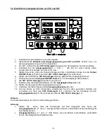
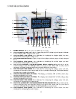
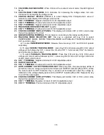
13.  CH4 OVERLOAD INDICATOR:

 When CH4 is at the constant current mode, this LED light will 

be on. 

14.  CH4  VOLTAGE  TUNE  KNOB:

  Turn  clockwise  for  increasing  the  voltage  value;  turn  anti-

clockwise for decreasing the voltage value. 

15.  CH2/CH4  DISPLAY  SWITCH:

  PRESS  it  to  select  display  CH4  Voltage/current  value  or 

release to select display CH2 voltage/current value. 

16. 

CH4 “-”TERMINAL:

 Negative terminal of 0-15V adjustable output. 

17. 

CH4 “+”TERMINAL:

 Positive terminal of 0-15V adjustable output. 

18. 

CH2 “-”TERMINAL:

 Negative terminal of 0-30V adjustable output. 

19.  TRACKING MODE SELECTION KEY

: see[23] 

20. 

CH2 “+”TERMINAL:

 Positive terminal of 0-30V adjustable output. 

21.  CH2/CH4 CURRENT DISPLAY PANEL:

 This display will indicate CH2 or CH4 current value 

that will be applied to the circuit 

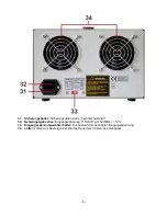
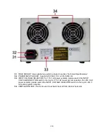
22.  GND GROUNDING TERMINAL:

 This terminal is connecting to the casing and the Earth. 

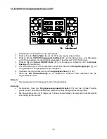
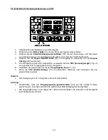
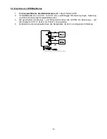
23.  TRACKING  MODE  SELECTION  KEY: 

this  key  is  operated  with  key  [19]  to  select 

INDEPENDENT MODE, SERIES TRACKING MODE and PARALLEL TRACKING MODE for 
CH1 and CH2 output. 


a)  To select 

INDEPENDENT MODE

:  Release these two  keys;  CH1  and  CH2  will  operate 

separately. 
   b) To select 

SERIES TRACKING MODE

 : press Key[19] and release key[23], CH2 output 

voltage will be followed by CH1, 

connect the circuit to CH1 “+” terminal and CH2 “-“terminal to 

get double rated voltage output. 
   c)  To  select 

PARALLEL  TRACKING  MODE

:  Press  Key  [19]  and  key  [23],  CH2  output 

voltage and current will be followed by CH1, connecting the circuit to CH1 will get 0-30V and 
double rated current output. 

24. 

CH1 “-”TERMINAL:

 Negative terminal of 0-30V adjustable output. 

25.  OUTPUT INDICATOR


26. 

CH1 “+”TERMINAL:

 Positive terminal of 0-30V adjustable output. 

27.  AUTO CURRENT CUT OFF PROTECTION KEY:

 After power ON, the power supply will be at 

protection state (no voltage output at all terminals and OUTPUT indicator [25] is OFF). When 
the  Auto  Current  Cut  Off  Protection  Key  is  pressed,  all  terminals  will  output  the  voltage  as 
indicated on the voltage display panel and the OUTPUT indicator [25] is ON. Repress the key 
to cut off the output again. 

28.  CH2/CH4 CURRENT DISPLAY PANEL

: This display will indicate CH2 or CH4 current value 

that will be applied to the circuit. 

29. 

CH3 “-” TERMINAL:

 Negative terminal of 0-6.5V adjustable output 

30. 

CH3 “+” TERMINAL:

 Positive terminal of 0-6.5V adjustable output 


-18- 

Содержание 6215

Страница 1: ...Bedienungsanleitung Operation manual Stabilisiertes 4 Kanal Labornetzgerät Regulated 4 Channel Laboratory Power Supply PeakTech 6215 ...

Страница 2: ...cken Keine Flüssigkeiten auf dem Gerät abstellen Kurzschlussgefahr beim Umkippen des Gerätes Gerät nicht in der Nähe starker magnetischer Felder Motoren Transformatoren usw betreiben Nehmen Sie das Gerät nie in Betrieb wenn es nicht völlig geschlossen ist Verwenden Sie ausschließlich 4mm Sicherheitstestkabelsätze um eine einwandfreie Funktion des Gerätes zu gewährleisten Messarbeiten nur in trocke...

Страница 3: ...r angepasst und können mit Hilfe der internen Schaltung automatisch parallel oder in Reihe geschaltet werden Somit ist der Betrieb bei in Reihe geschalteten Ausgänge beträgt die maximale Ausgangsspannung 60 V bei parallel geschalteten Ausgängen beträgt der maximale Ausgangsstrom 10 A Mit dieser hohen Stabilität ist dieses Netzteil für den Einsatz in Schulen Ausbildung Labor Universität und im Serv...

Страница 4: ...wert zu verringern 6 CH1 CV CC Konstantspannung Konstantstrom Anzeige Wenn sich CH1 im Konstantspannungsbetrieb befindet leuchtet diese LED grün auf Wenn sich CH1 im Konstantstrombetrieb befindet und im Parallel Modus geschaltet ist wird diese LED rot aufleuchten 7 CH1 Spannungsregler Im Uhrzeigersinn drehen zur Erhöhung Ausgangspannung gegen den Uhrzeigersinn drehen um den Spannungswert zu verrin...

Страница 5: ...em Gehäuse und der Erde verbunden 23 Auswahltasten des Betriebsmodus Auswahl der Betriebsarten NORMAL SERIES und PARALLEL a NORMAL Modus beide Tasten auf AUS CH1 und CH2 werden getrennt betrieben und sind separat voneinander einstellbar und belastbar b SERIES Modus Reihenbetrieb Drücken Sie die Taste 19 und belassen Sie die Taste 23 auf AUS Die Auswahl der Ausgangswerte Spannung Strom wird über di...

Страница 6: ... siehe Technische Daten 32 Netzeingangsbuchse Eingangsspannung 115 230V AC 50 60Hz 10 33 Eingangsspannungswahlschalter Zur Auswahl der benötigten Eingangsspannung 34 Lüfter Lüfter zum Absaugen der Warmluft aus dem Inneren des Gehäuses 5 ...

Страница 7: ...zu erfüllen Kanal 1 und 2 Stabilität Reihenbetrieb Parallelbetrieb CV Modus CH1 und CH2 1 x 10 4 3mV 10 der Nennspannung CC Modus CH1 und CH2 2 x 10 3 3mA 1 x 10 4 3mV 1 x 10 4 5mV Laststabilität Temperaturkoeffizient V Reihenbetrieb Parallelbetrieb CV Modus CH1 und CH2 2 x 10 4 5 mV I 3 A 2 x 10 4 10mV I 3 A CC Modus CH1 und CH2 2 x 10 3 5 mA I 3 A 300 ppm C 2 x 10 4 5 mV I 3 A 2 x 10 4 10 mV I 3...

Страница 8: ... Um die Spannung an CH2 einzustellen wiederholen Sie die oben genannten Schritte und verwenden Sie dann den CH2 Spannungsregler 10 verbinden Sie die Schaltung mit den Ausgangsbuchsen 18 20 und beachten Sie die CH2 CV CC Anzeige 11 Hinweis Wenn CH2 nicht eingestellt werden kann überprüfen Sie dass die Auswahltasten des Betriebsmodus 19 23 nicht gedrückt sind und das Gerät evtl im SERIES oder PARALL...

Страница 9: ... erneut die Output ON OFF Taste 27 um die Ausgänge abzuschalten 8 Die CH1 CV CC Anzeige 6 leuchtet nun grün auf 9 Entfernen Sie die Kurzschlussleitung von den Ausgangsbuchsen 26 24 10 Stellen Sie die gewünschte Ausgangsspannung ein 11 Verbinden Sie die Schaltung mit den Ausgangsbuchsen 26 24 12 Um den Strom an CH2 einzustellen wiederholen Sie die oben genannten Schritte und verwenden Sie dann den ...

Страница 10: ... die Spannung am CH3 einzustellen verwenden Sie den CH3 Spannungsregler 3 um eine gewünschte Ausgangsspannung vorzugeben 6 Verbinden Sie den Stromkreis mit den Ausgangsbuchsen 30 29 7 Wenn die CH3 Überlastanzeige 4 rot aufleuchtet entfernen oder reduzieren Sie die angeschlossene Last Hinweis Stromausgang ist auf 3 A begrenzt und nicht veränderbar Achtung Sicherstellen dass der Eingangsspannungswah...

Страница 11: ...die Spannung am CH4 einzustellen verwenden Sie den CH4 Spannungsregler 14 um eine gewünschte Ausgangsspannung vorzugeben 6 Verbinden Sie den Stromkreis mit den Ausgangsbuchsen 17 16 7 Wenn die CH4 Überlastanzeige 13 rot aufleuchtet entfernen oder reduzieren Sie die angeschlossene Last Hinweis Stromausgang ist auf 1 A begrenzt und nicht veränderbar Achtung Sicherstellen dass der Eingangsspannungswa...

Страница 12: ...nabhängige Stromversorgungen Spannung und Strom können separat eingestellt werden 3 Die gewünschten Spannungs und Stromwerte können Sie mit Hilfe der Spannungs und Stromregler für CH1 7 5 bzw für CH2 10 12 einstellen 4 Verbinden Sie die Ausgangsbuchsen des Netzgerätes mit der zu versorgenden Schaltung Illustration of independent mode 11 ...

Страница 13: ...Ausgangsstrom einzustellen und verwenden Sie dann den CH1 Stromregler 4 um den gewünschten Stromausgangswert einzustellen siehe auch Einstellen des Ausgangsstromes von CH1 und CH2 3 Verwenden Sie den CH1 Spannungsregler 7 um den gewünschten Spannungswert einzustellen 4 Verbinden Sie die zu versorgenden Schaltung an die Ausgangsbuchsen CH1 26 und CH2 24 um die doppelte Ausgangsspannung zu erhalten ...

Страница 14: ...rwenden Sie den CH1 Spannungsregler 7 um den gewünschten Spannungswert einzustellen 3 Drehen Sie den CH2 Stromregler 12 im Uhrzeigersinn um den maximalen Ausgangsstrom einzustellen und verwenden Sie dann den CH1 Stromregler 5 um den gewünschten Stromausgangswert einzustellen siehe auch Einstellen des Ausgangsstromes von CH1 und CH2 4 Verbinden Sie die zu versorgenden Schaltung an die Ausgangsbuchs...

Страница 15: ...gshalter wieder in die Netzeingangsbuchse Achten Sie darauf dass diese einrastet und festen Kontakt hat Alle Rechte auch die der Übersetzung des Nachdruckes und der Vervielfältigung dieser Anleitung oder Teilen daraus vorbehalten Reproduktionen jeder Art Fotokopie Mikrofilm oder ein anderes Verfahren nur mit schriftlicher Genehmigung des Herausgebers gestattet Letzter Stand bei Drucklegung Technis...

Страница 16: ... operate the meter before the cabinet has been closed and screwed safely as terminal can carry voltage Please use only 4mm safety test leads to ensure immaculate function To avoid electric shock do not operate this product in wet or damp conditions Conduct measuring works only in dry clothing and rubber shoes i e on isolating mats Never touch the tips of the test leads or probe Comply with the war...

Страница 17: ...ode has the maximum output voltage of 60 V in parallel operation the maximum output current is 10 A The high stability of this power supply is suitable for use in schools training laboratory university and service 1 1 Main Features 4 adjustable Channels 0 30 V Linear Voltage and Current Output Display 4 x 4 digit LED displays for Voltage and Current Output Display Low Ripple and Noise Voltage and ...

Страница 18: ...VOLTAGE TUNE KNOB Turn clockwise for increasing the voltage value turn anti clockwise for decreasing the voltage value When in SERIES PARALLEL TRACKING MODE use this knob to adjust CH2 voltage 8 CH1 CH3 VOLTAGE DISPLAY PANEL This display will indicate CH1 or CH3 current value that will be applied to the circuit 9 CH2 CH4 VOLTAGE DISPLAY PANEL This display will indicate CH2 or CH4 voltage value tha...

Страница 19: ...NT MODE Release these two keys CH1 and CH2 will operate separately b To select SERIES TRACKING MODE press Key 19 and release key 23 CH2 output voltage will be followed by CH1 connect the circuit to CH1 terminal and CH2 terminal to get double rated voltage output c To select PARALLEL TRACKING MODE Press Key 19 and key 23 CH2 output voltage and current will be followed by CH1 connecting the circuit ...

Страница 20: ...PUT VOLTAGE SELECTOR For 115 V AC power systems please switch the INPUT VOLTAGE SELECTOR switch to the top for 115 V AC power system selection For 230 V AC power systems please switch the INPUT VOLTAGE SELECTOR switch to the top for 230 V AC power system selection 34 VENTILATION FAN This fan is used to exhaust heat air from internal heat sink 19 ...

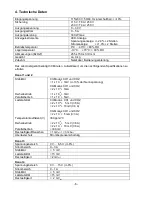
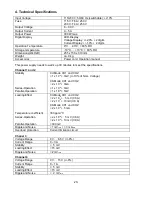
Страница 21: ...el 1 and 2 Stability Series Operation Parallel Operation CV Mode CH1 and CH2 1 x 10 4 3mV 10 of Nom Voltage CC Mode CH1 and CH2 2 x 10 3 3mA 1 x 10 4 3mV 1 x 10 4 5mV Loading Effect Temperature coefficient Series Operation Parallel Operation CV Mode CH1 und CH2 2 x 10 4 5 mV I 3 A 2 x 10 4 10mV I 3 A CC Mode CH1 und CH2 2 x 10 3 5 mA 300 ppm C 2 x 10 4 5 mV I 3 A 2 x 10 4 10 mV I 3 A 300 mV Ripple...

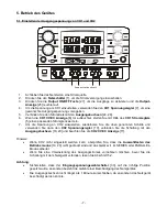
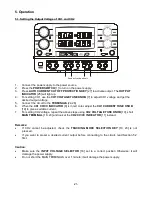
Страница 22: ...he CH1 CV CC INDICATOR 6 is in red color adjust the CH1 CURRENT TUNE KNOB 19 to give a suitable current 7 For setting CH2 voltage repeat the above steps using CH2 VOLTAGE TUNE KNOB 10 short MAIN TERMINAL 18 20 and look at the CH2 CV CC INDICATOR 11 instead Remarks If CH2 cannot be adjusted check the TRACKING MODE SELECTION KEY 19 23 is not pressed If you want to preset a desired current output bef...

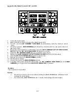
Страница 23: ...CH1 CURRENT KNOB 5 to give a desired output current 7 Repress the AUTO CURRENT CUT OFF PROTECTION KEY 27 to Cut off the output 8 Then the CH1 CV CC INDICATOR 6 will turn to green color 9 Remove the conductor the MAIN TERMINAL 26 24 10 Set the desired voltage 11 Connect the circuit to the MAIN TERMINAL 26 24 12 To setting CH2 current repeat the above steps use CH2 CURRENT TUNE KNOB 12 short MAIN TE...

Страница 24: ...and the OUTPUT INDICATOR 25 will on 5 Use the CH3 VOLTAGE KNOB 3 to adjust CH3 voltage to give a desired output voltage 6 Connect the circuit to the CH3 TERMINAL 30 29 7 When the CH3 OVERLOAD INDICATOR 4 is on remove some loading on the terminal to reduce current consumption Remarks Current output is fixed to 3 A not adjustable Caution Make sure the INPUT VOLTAGE SELECTOR 33 set to a correct posit...

Страница 25: ...and the OUTPUT INDICATOR 25 will on 5 Use the CH4 VOLTAGE KNOB 14 to adjust CH4 voltage to give a desired output voltage 6 Connect the circuit to the CH4 TERMINAL 17 16 7 When the CH4 OVERLOAD INDICATOR 13 is on remove some loading on the terminal to reduce current consumption Remarks Current output is fixed to 1A not adjustable Caution Make sure the INPUT VOLTAGE SELECTOR 33 set to a correct posi...

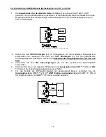
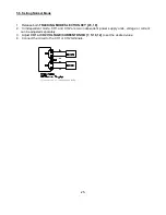
Страница 26: ...n independent mode CH1 and CH2 are two independent power supply units voltage or current can be adjusted separately 3 Adjust CH1 or CH2 VOLTAGE CURRENT KNOB 7 5 10 12 to set the desired value 4 Connect the circuit to the CH1 or CH2 terminals Illustration of independent mode 25 ...

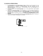
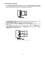
Страница 27: ...T KNOB 12 clockwise to maximum current output and then use CH1 CURRENT KNOB 5 adjust the desired current output value Reference to Section 5 2 3 Use CH1 VOLTAGE KNOB 7 to adjust the desired voltage output value 4 Connect the circuit to the CH1 TERMINAL 26 and CH2 TERMINAL 24 to get double voltage output 5 For the bi polar DC power supply with common ground connect CH2 TERMINAL 20 to GND GROUNDING ...

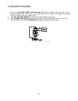
Страница 28: ...d current value follows CH1 setting The output current is double to the CH1 display value 2 Use CH1 VOLTAGE KNOB 7 to adjust the desired voltage output value 3 CH1 CURRENT KNOB 12 adjust the desired current output value Reference to Section 4 2 4 Connect the circuit to the CH1 TERMINAL 26 24 to get double current output Illustration of Parallel Tracking Mode 27 ...

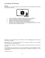
Страница 29: ...ket All rights also for translation reprinting and copy of this manual or parts are reserved Reproductions of all kinds photocopy microfilm or other only by written permission of the publisher This manual is according the latest technical knowing Technical alterations reserved We herewith confirm that the units are calibrated by the factory according to the specifications as per the technical spec...

Отзывы: