background image

Page 23

Commissioning & Safe Start-Up Sequence

With reference to the diagram in the 

Recommended Piping Layout

 section. 

Once the generator has been installed, DO NOT Switch on the power immediately. It is 

recommended that the inlet compressed air supply valve (1) remains closed, and that 

the inlet bypass valve (2) is opened slightly to sufficiently allow the inlet compressed 

air to vent and purge any remaining moisture from the newly installed pipework (if this 

is the first operation of the compressed air supply, it is recommended that the air be 

vented for a minimum of 2hrs to allow the air filtration and dryer to stabilise).  
Once the inlet pipework has been purged, the inlet bypass valve (2) can then be 

closed and the pressure gradually introduced to the generator by slowly opening 

the compressed air inlet (1) valve. The outlet bypass valve (3) should now be open to 

atmosphere, and the delivery valve (4) to the customer application should be closed. 

Ensure that both Process Tank Isolation valves (5) are both fully open. 
The power can then be turned on. On first start up air will be introduced to Column 

1 and the front panel gauge will slowly start to rise. The front panel display will show 

a message “COLUMN 1” and a timer counting up. After approx. 30 to 80 seconds 

(timing will vary depending on your specific performance requirements) the front panel 

display will briefly show an “EQUALIZING” message and the pressure on Column 1 and 

2 gauges should level out. Column 1 will then vent rapidly to zero and column 2 will 

continue to rise slowly. During this process the TANK pressure gauge should continue 

to slowly rise. Allow the Nitrogen Process Gas Tank to reach pressure, then continue 

to vent the outlet gas through the bypass valve (3) for a minimum of 4 hours (ideally 

this should be done overnight to fully purge all the remaining oxygen/moisture in the 

system). 
The Generator has been pre-set in the factory to give the specified output flow-rate 

and pressure. Failure to achieve the factory specification after maintenance may be as 

a result of an incorrect service procedure, please review any maintenance carried out. 

If unable to achieve specification contact Peak Gas Generation for further assistance. 

After this time the outlet bypass valve (3) can be closed, and the delivery valve (4) to 

the customer application should be slowly opened to pressurize the line.
The design of the generator is that it will deliver up to your specific output pressure and 

flow of nitrogen. Should the demand for Nitrogen be less than the rated output flow, 

or indeed should the demand stop the generator will automatically go into ECO Mode 

and the front panel LED will illuminate. In ECO mode the changeover of the columns is 

suspended which will stop the consumption of inlet compressed air. The control system 

will automatically detect when the demand resumes and the generator will start to 

produce nitrogen again. 

Содержание i-Flow 6000 Series

Страница 1: ...i Flow 6000 Series User Manual Copyright Peak Scientific Instruments Ltd 2021 i Flow 6000 Series User Manual Rev 15 RSID 175 PN UM00018 EN copy 30 11 2021...

Страница 2: ...Declaration 11 Technical Specification 12 Unpacking 14 Installation 15 Generator Environment 15 Generator 16 General Dimensions 16 Inlet Outlet Connections 17 Unit Controls 17 Compressed Air Quality...

Страница 3: ...larations Update L Couttie 10 11 2020 13 Declarations Update L Couttie 18 12 2020 14 Declarations Update D Lai 12 10 2021 How to use this Manual This manual is intended for end users and has been writ...

Страница 4: ...d to meet your specific pressure flow and purity requirements if you have any questions regarding the sizing of your system please do not hesitate to contact Peak Gas Generation or the Peak Partner fr...

Страница 5: ...gen and regenerate the bed in preparation for the next cycle This will continue to alternate and repeat until the user stops consuming nitrogen Should the demand for nitrogen be less than the rated ou...

Страница 6: ...e Basic Unit 1 i Flow Oxygen Analyser 2 i Flow PPM Oxygen Analyser 3 Inlet Outlet Filter No Oxygen Analyser 4 Inlet Outlet Filter Oxygen Analyser 5 Inlet Outlet Filter PPM Oxygen Analyser 6 i Flow Lab...

Страница 7: ...en commissioned by Peak or a Peak Partner c the feed air or inlet air supply to the generator must comply with ISO 8573 1 2010 Class 1 2 1 at all times d your air compressor dryer filtration and oil r...

Страница 8: ...is invalidated for whatever reason such part will be deleted and the rest shall remain unaffected continuing to be in full force and effect Delivery of Warranty Service 12 Subject to clause 13 and a...

Страница 9: ...or adhered to could cause damage to the Generator or the Application Do not proceed beyond a CAUTION notice until the indicated conditions are fully understood or met Caution risk of electric shock E...

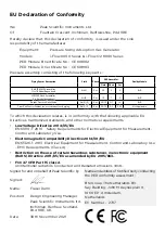
Страница 10: ...ping Front End Control Cabinet inc associated valves piping Air N Air N2 2 O O2 2 Gas Gas 2G 1G 2G 1G 2 1 2 1 SEP SEP Not Applicable Not Applicable To which this declaration relates is in conformity w...

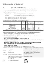
Страница 11: ...piping Front End Control Cabinet inc associated valves piping Air N Air N2 2 O O2 2 Gas Gas 2G 1G 2G 1G 2 1 2 1 SEP SEP Not Applicable Not Applicable To which this declaration relates is in conformity...

Страница 12: ...ance Notes PDF produced by the Department for Business Innovation and skills for the UK and here for Europe All PEAK products that are subject to the WEEE directive are compliant with the WEEE marking...

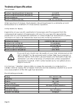
Страница 13: ...6barg Maximum Inlet Air Pressure 145 psig 10barg Minimum Inlet Air Temperature 5 C 41 F Maximum Inlet Air Temperature 35 C 95 F If you are in any doubt over the quality of your inlet compressed air D...

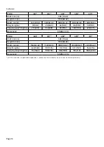
Страница 14: ...801 451 992 538 1184 625 1375 Noise level 59 dBA 1m Model 606 607 608 609 610 Width mm in 500 19 68 Height mm in 1738 68 42 Depth mm in 1560 61 42 1720 67 72 1880 74 02 2040 80 31 2200 86 61 Weight kg...

Страница 15: ...it is advisable to fully inspect the unit for any sign of transit damage Check SHOCKWATCH and TIP N TELL labels for signs of rough handling prior to unpacking Any damage should be reported immediately...

Страница 16: ...floor Depending on the generator model you will have 4 or 8 fixing positions Typically 10mm or 3 8 floor fixings approx 75mm or 3 in length will be suitable on most concrete floors Generator Environme...

Страница 17: ...imensions Note Each additional bank assembly 160mm 6 3 The Generator must always be placed on a level surface Failure to do so will affect the stability of the Generator 2200 mm 86 6 1738mm 68 4 WARNI...

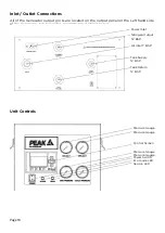
Страница 18: ...panel on the Left hand side of the Generator See below for recommended piping layout Unit Controls Power Inlet Nitrogen Output BSP Air Inlet 1 BSP Tank Supply BSP Tank Return BSP Pressure Gauge Press...

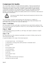
Страница 19: ...iltration system the inlet air quality must meet a minimum of IS0 8573 1 2010 class 1 2 1 Class 1 2 1 is further defined as Class 1 Particulate Per cubic meter of air the particulate count should not...

Страница 20: ...r to your quotation documents for details of the items we have recommended to meet your specific requirements Should you require any further assistance or support please do not hesitate to contact Pea...

Страница 21: ...by a qualified electrician DO NOT USE inadequately rated detachable Mains cords This unit is classified as SAFETY CLASS 1 THIS UNIT MUST BE EARTHED Before connecting the unit to the mains supply plea...

Страница 22: ...portant to include bypass valves at the generator inlet nitrogen outlet of the system It is also recommended that a non return valve be fitted on the exit of the system to prevent downstream pressure...

Страница 23: ...isplay will briefly show an EQUALIZING message and the pressure on Column 1 and 2 gauges should level out Column 1 will then vent rapidly to zero and column 2 will continue to rise slowly During this...

Страница 24: ...plugs must NOT be removed whilst the system is under pressure If removed it is likely that pressure will be released violently and cause injury Safe Isolation Process To shut the system down close th...

Страница 25: ...mponent Part No Quantity 601 605 606 610 12 months Vent Silencer Element 02 5710 2 4 Pneumatic Valve Exhaust Silencer 02 1016 5 7 N2 Supply NRV 02 5620 2 2 48 months O2 Analyser 04 4571 1 1 O2 Analyse...

Страница 26: ...to install and setup your generator IQ OQ Certified assurance for applications requiring documented qualification Complete plan Swift response by a Peak Service Engineer within 72 hours planned preven...

Страница 27: ...or material contained within it If there is any doubt about the compatibility of decontamination or cleaning agents please contact your Peak Gas Generation representative Cleaning should only be under...

Страница 28: ...hat remain unregistered after 1 month from the shipment date the warranty will be considered active from the date of factory dispatch Complete Plan only Go Online or Complete and Return We know that r...

Страница 29: ...rtified to the current in force revision of the following standards in order to cover both Canadian and United States requirements for Safety Requirements for Electrical Equipment for Measurement Cont...

Страница 30: ...eliver a program of scheduled preventative maintenance whilst giving you the reassurance of instant access to worldwide technical support and priority on site response in the untimely event of a break...

Отзывы: