background image

67

L510010-03

C.C.

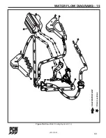
Figure 15-2 

Fresh-Water Cooling System (5.0/5.7L)

WATER FLOW DIAGRAMS - 15

=

R

A

W

W

A

TER

FLOW

=

F

RESH

W

A

TER

FLOW

T

o

Cylinder

Block

T

o

Cylinder

Block

From

Intake

Manifold

=

Drain

Locations

Содержание 2003 5.0L MPI

Страница 1: ...OWNER S OPERATION and MAINTENANCE MANUAL A Division of ...

Страница 2: ...ssion computerized engine control and the Fuel Control Cell FCC are all PCM innovations No matter which PCM model you purchased you can be sure it is equipped with the latest in modern technology for added performance and durability READ THIS MANUAL THOROUGHLY Before starting your engine s READ THIS MANUAL CAREFULLY AND COMPLETELY If you do not understand any portion of the manual contact your Dea...

Страница 3: ......

Страница 4: ... Information 13 2003 Model Identification Advisory 14 ELECTRONIC FUEL INJECTION INFORMATION 15 Electronic Fuel Injection System 15 Power Reduction Mode 15 OPERATING INSTRUCTIONS 16 20 Engine Alarm System 16 Instrumentation 17 Starting Engine Fuel Injected Engines 18 Shifting Transmission 19 Stopping Engine 20 Freezing Temperature Operation 20 Operation in High Debris Areas 20 CONDITIONS AFFECTING ...

Страница 5: ...ystem Description 38 Fuel Control Cell FCC Fuel System 38 Servicing the FCC 39 Draining the FCC Bowl ENGINE OFF 40 Filter Element Replacement ENGINE OFF 40 Primary Fuel Filter 41 Priming Fuel System 42 Flame Arrestor 42 Accessory Drive Belt 43 46 Changing Oils 47 Engine Alignment 47 50 Engine Maintenance Log 51 Maintenance Schedule 52 Visual Inspection 54 Engine Fluid Capacities 54 Transmission Fl...

Страница 6: ...er Survey We appreciate your feedback and encourage you to fill out the survey after you have had a chance to run your boat for several weeks We take this input very seriously and have implemented many of the ideas our customers have given us through this survey You may also visit our website at www pleasurecraft com Again thanks for choosing PCM We sincerely wish you happy days on the water INTRO...

Страница 7: ...ir effectiveness is reduced by an extended storage period prior to sale or use C Components supplied by the Ford Motor Co are warranted by the Industrial Engine Division of the Ford Motor Co and are not covered by this Warranty OBTAINING PERFORMANCE UNDER WARRANTY PCM s warranty registration form should be prepared by your selling dealer executed by you and the dealer and mailed by you to PCM with...

Страница 8: ...ng diagnosis parts and labor MANUFACTURER S WARRANTY COVERAGE Select emission control parts from Model Years 2003 2008 inboard engines are warranted for 2 years OWNER S WARRANTY RESPONSIBILITIES As the inboard engine owner you are responsible for the performance of the required maintenance listed in your owner s manual Pleasurecraft recommends that you retain all receipts covering maintenance on y...

Страница 9: ... Pleasurecraft warranty station The repair or replacement will be performed at no charge to the owner Any such part repaired or replaced under this Warranty will be warranted for the remainder of the two 2 year period 4 Any part covered under this Warranty that is scheduled only for regular inspection in the written instruc tions to be found within the Pleasurecraft Owners Operators Manual is warr...

Страница 10: ...eligible for coverage under this Warranty may be excluded from such warranty coverage if Pleasurecraft demonstrates that the engine and or part has been abused neglected or improperly maintained and that such abuse neglect or improper maintenance was the direct cause of the need for repair or replacement of the part 11 Pleasurecraft original equipment parts are identical in all material respects t...

Страница 11: ...8 L510010 03 C C This Page Was Intentionally Left Blank INTRODUCTION 1 ...

Страница 12: ...pproved could cause a fire or explosion hazard and should be avoided Always request that genuine PCM Engines replacement parts be used in any repairs or maintenance being performed on your engine s DANGER Electrical ignition and fuel system components are designed and manufactured to comply with U S Coast Guard rules and regulations to minimize the possibility of fire or explosion hazard DANGER Si...

Страница 13: ...tion reveals possible leaks DO NOT operate your engine s until it can be serviced by a qualified technician Proper and adequate air circulation around and throughout the boat is absolutely necessary to aid in the prevention of carbon monoxide build up If you have any questions or concerns regarding the operation of your boat and carbon monoxide hazards DO NOT operate your engines until you have co...

Страница 14: ...as whenever possible Follow the Rules of the Road when boating Always be on the alert and watch out for the other guy Plan and chart your course Be aware of and avoid hazardous areas Be sure your boat is equipped with the required safety equipment Check with the Coast Guard and local government agencies as to the regulations and restrictions in your area Contact your local Coast Guard Auxiliary an...

Страница 15: ...f the boat that are designed for that purpose If water is rough carry fewer passengers Observe the Rules of the Road PORT Left Leaving the harbor with green buoys to your right STARBOARD Right Entering the harbor with red buoys to your right Know Your Horn Signals 1 Short Blast Passing you on my port side 2 Short Blasts Passing you on my starboard side 3 Short Blasts I am going astern 5 Short Blas...

Страница 16: ...TURE LITTLE MOUNTAIN SC 29075 1 ENGINE SPECIFICATION DECAL 2 ENGINE IDENTIFICATION DECAL 3 TRANSMISSION IDENTIFICATION PLATE 3 2 2 1 OIL TYPE DEXRON III HIGHWAY 76 EAST LITTLE MOUNTAIN S C 29075 SERIAL No MODEL MARINE POWER RATIO CHECK OIL LEVEL DAILY OIL CHANGE AFTER FIRST 25 HOURS OF OPERATION AND EVERY 100 HOURS OR 12 MONTHS WHICHEVER OCCURS FIRST IMPORTANT NOTE WARRANTY IS VOID IF MAINTENANCE ...

Страница 17: ...UEL INJECTION SERIAL NUMBER I D 1st DIGIT INDICATES DECADE ENGINE WAS MANUFACTURED 3 1990 4 2000 5 2010 2nd DIGIT INDICATES YEAR ENGINE WAS MANUFACTURED 1st Space MANUFACTURER P Pleasurecraft Marine 2nd Space FACTORY FRESHWATER CLOSED COOLING X Freshwater Cooled Space Omitted If Raw Water Cooled 3rd Space ENGINE ROTATION L Rotation Left Hand from Rear R Rotation Right Hand from Rear 4th Space ENGI...

Страница 18: ... Sensor Knock Sensor KS System Crankshaft Positioning CKP Sensor Camshaft Positioning CMP Sensor Intake Air Temperature IAT Sensor POWER REDUCTION MODE The ECM monitors engine oil pressure and engine coolant temperature whenever the engine is running If either one of these inputs indicate an abnormal reading the system will go into Power Reduction mode followed by the illumination of an indicator ...

Страница 19: ...f checking feature programmed into the system This feature will sound the alarm for two short pulses upon initial start up of the engine If the alarm sounds during operation immediately throttle back to idle speed Observe the indicator lamps to locate the problem circuit The engine should be shut off to prevent damage to the engine NOTICE Some boat builders may install their own alarm system It is...

Страница 20: ...brief explanation of typical instrumentation found on most boats 1 Tachometer indicates the engine RPM revolutions per minute 2 Engine Synchronizer twin engines only 3 Water Temperature Gauge indicates the engine coolant temperature 4 Oil Pressure Gauge indicates the engine oil pressure 5 Voltmeter indicates the battery voltage and charging system voltage 6 Hour Meter indicates the engine operatin...

Страница 21: ...the ECM will command the injectors to deliver no fuel during engine cranking When the engine starts return the throttle lever back to the idle position IMPORTANT If the engine fails to start within 20 30 seconds turn the ignition key to the OFF position and allow 2 minutes for the starter motor to cool off before attempting to restart the engine IMPORTANT Do not start the engine without water bein...

Страница 22: ...sure the engine is operating within the normal temperature range If the temperature is abnormally high stop the engine immediately and determine the cause SHIFTING TRANSMISSION CAUTION Never shift the transmission into or out of gear unless the throttle is at the idle position Shifting the transmission above 1000 RPM can severely damage the boat transmission and engine 1 Set the throttle lever at ...

Страница 23: ... valve 3 Close the seacock 4 Flush the cooling system if in a salt water area OPERATING INSTRUCTIONS 5 FREEZING TEMPERATURE OPERATION If the possibility of freezing exists the cooling system must be protected after the engine is shut off to prevent freeze damage to the engine Refer to OUT OF SEASON STORAGE for draining instructions OPERATION IN HIGH DEBRIS AREAS If the boat is to be operated in hi...

Страница 24: ...or cruising running against a choppy wave condition acceleration onto plane and operating at slow planing speeds Will improve rough water ride and handling In extreme may cause the boat to bow steer veer back and forth with little control CONDITIONS AFFECTING OPERATION 6 BOAT BOTTOM To ensure maximum engine performance fuel economy and boat speed the bottom of your boat must be kept clean and free...

Страница 25: ...aneous gear is one of the major factors and should be one of the primary considerations when selecting a propeller Other factors to take into consideration are as follows Warmer weather and higher humidity will cause an RPM loss Operating the boat in a higher elevation will cause an RPM loss Operating the boat with an increased load will cause an RPM loss additional equipment passengers etc If ful...

Страница 26: ...ner s responsibility WARNING Use this procedure ONLY when conditions are such that it can be done in complete safety Reduce the throttle to 2800 3000 RPM and cruise at or below this speed for 1 2 hour Reduce the speed to idle Go to wide open throttle until maximum RPM is reached and operate for approximately 1 minute Reduce throttle to 2800 3000 RPM and operate for a few minutes Bringing the engin...

Страница 27: ...eck the throttle and the shift cable adjustments and check for freedom of movement Cooling System Inspect all the hoses for leaks damage and deterioration Check all the hose clamps for adequate tightness Exhaust System Inspect the entire exhaust system for leaks damage and deterioration Check all the hose clamps for adequate tightness Battery Check the electrolyte level and specific gravity Inspec...

Страница 28: ... containing alcohol either ethanol ethyl alcohol or methanol methyl alcohol is not recommended for use in your engine Gasoline containing alcohol will attract and hold moisture and may cause the following Hard starting and operating difficulties vapor lock low speed stalling Corrosion of metal parts Excessive wear and damage to internal engine parts Fuel permeation through flexible fuel lines Dete...

Страница 29: ... the recommended oil viscosity for various ambient temperature ranges Prevailing Ambient Recommended A P I Temperature Classification Viscosity Above 50 F SAE 15W 40 SJ Below 50 F SAE 5W 30 SJ IMPORTANT The use of oils which contain solid additives non detergent oils or low quality oils specifically are not recommended WARRANTY NOTICE PCM Engines reserves the right to refuse warranty on part s and...

Страница 30: ...e oil pressure and may result in internal engine damage from lack of lubrication 1 Stop the engine if running Allow approximately 5 minutes for the oil to drain back into the oil pan 2 Remove the dipstick wipe it clean and reinstall it fully into the dipstick tube 3 Remove the dipstick and observe the oil level The oil level must be between the FULL and ADD marks If the oil level is below the ADD ...

Страница 31: ...rop shaft not turning install the dipstick in all the way 4 Remove the dipstick and check the fluid level The dipstick should read FULL 5 If the fluid level is low add in small increments until the FULL mark is reached 6 It is normal after the engine is turned OFF for the level to read above the FULL mark 1 Remove the dipstick by turning the T handle counterclockwise Observe the fluid level Replac...

Страница 32: ... points and exposed cable Figure 11 3 with SAE 30W 30 engine oil Figure 11 3 Typical Throttle Cable Shift Cable Lubricate pivot points and exposed cable Figure 11 4 with SAE 30W 30 engine oil Figure 11 4 Typical Shift Cable CABLE CLIP BALL JOINT LUBRICATION POINTS LUBRICATION POINTS ...

Страница 33: ...d shorted circuits ELECTRICAL SYSTEM FUSES PCM engines utilizes fuses to control the fuel pump ECM and fuel injectors The fuse block is mounted to a bracket near the exhaust elbow under a weather tight cover Figure 11 5 Typical Electrical System Circuit Breaker and Fuses IGNITION FUSE If the engine will not crank when the ignition key is turned to the START position first check that the shift leve...

Страница 34: ... and recharge in a well ventilated area away from fuel vapors sparks and open flames Follow maintenance instructions and warnings as supplied by the battery manufacturer If this information is not available follow these guidelines for the proper battery care Do not operate the engine with an open in the battery circuit as this may cause damage to the alternator Make sure that all connections are c...

Страница 35: ...one replace with a new zinc anode Different geographic locations and water make up can result in either high or low sacrificial requirements A high rate of zinc anode consumption should also alert the owner to a possibility of an improperly wired boat accessory which would require complete checking by qualified service personnel Figure 11 6 Zinc Anode Location F W C Heat Exchanger 8 1L FULL ADD P ...

Страница 36: ...hat expands with rising temperature and would otherwise overflow from the system Coolant level should be at or slightly above the ADD mark on the bottle when the system is cold Coolant should be added ONLY to the reservoir when the system cools Coolant Filler Neck Periodically on a cool engine remove the pressure cap from the filler neck to ensure the coolant recovery system is functioning properl...

Страница 37: ...t hose CAUTION Do not operate the engine without sufficient amount of water being supplied to the sea water pump The sea water pump impeller may be damaged and subsequent overheating damage may result Figure 11 8 Typical Sea Water Inlet CAUTION Do not run the engine above 1500 RPM when flushing Suction created by the sea water pump may collapse the flushing hose causing the engine to overheat Watc...

Страница 38: ...s red the coolant is not alkaline and must be replaced DRAINING FRESH WATER COOLING SYSTEM NOTICE To protect the environment dispose of coolant properly Check your local restrictions for proper disposal instructions of removed coolant NOTICE Refer to cooling system water flow diagrams for drain locations 1 Remove the following drain plugs to drain coolant from the fresh water cooling system Drain ...

Страница 39: ...tem must be immediately drained and flushed and refilled with DEX COOL No short term damage will occur however the service interval will be reduced from 5 years to 2 years The fresh water cooling side of the cooling system must be filled with a 50 50 mixture of DEX COOL or equivalent which meets GM6277M extended life antifreeze and water solution IMPORTANT More than 50 antifreeze solution can cont...

Страница 40: ...the bolts securing the heat exchanger end plates Remove the end plates and gaskets 2 Clean the water passages in the heat exchanger by inserting a suitable size wire brush into each passage Use compressed air to blow out loose particles 3 Clean the gasket surfaces on the end plates and the heat exchanger Apply PerfectSeal to both sides of the new gaskets Install the end plates and the new gaskets ...

Страница 41: ...l at a volume much greater than the fuel flow rate required of the high pressure pump and engine demands The high pressure pump mounted inside the FCC bowl provides the necessary fuel pressure and volume to maintain proper engine performance The FCC constantly has an ample supply of fuel to meet the idle cruise and acceleration fuel requirements of the engine The fuel pressure regulator located on...

Страница 42: ...ement at least once a year or when a loss of power is noticed whichever occurs first WARNING Improper use installation or servicing may cause an explosion or fire resulting in bodily injury or death This unit should only be serviced by a qualified technician Read and follow all instructions before proceeding Run the engine and check for fuel leaks after installation element replacement or draining...

Страница 43: ...electrical connector 2 Hold the 3 4 jam nut located at the bottom of the FCC bowl with a wrench Remove the 7 16 plug and drain the bowl contents into an approved container CAUTION Both fuel and water will drain from the FCC bowl 3 Using a strap type oil filter wrench remove the FCC bowl by turning it counterclockwise as view from the bottom 4 Slide the bowl downward over the suspended filter eleme...

Страница 44: ...the FCC bowl and by hand thread the FCC bowl into the FCC mounting head Tighten the bowl firmly back into the mounting head with an oil filter wrench 12 Reconnect the two wire electrical connector 13 Cycle the ignition key several times to run the electric fuel pumps and fill the FCC bowl with fuel Inspect the drain plug area for leaks Correct any leaks prior to operating the engine 14 Start the e...

Страница 45: ... the engine does not start repeat the priming procedures FLAME ARRESTOR At specified intervals the flame arrestor should be checked for blockage caused by dirt or other foreign material Loosen the clamp securing the flame arrestor to the air intake tube or throttle body Remove the flame arrestor Clean the flame arrestor with solvent and dry with compressed air Reinstall the flame arrestor and tigh...

Страница 46: ...r pump and alternator CAUTION The replacement of the drive belt requires the removal of the inlet hose from the sea water pump With the hose removed it is possible for water to enter the bilge of the boat and possibly sink it ALWAYS plug the inlet hose securely to prevent this possibility from occurring DRIVE BELT REPLACEMENT 8 1L 1 Remove the inlet and outlet hoses from the sea water pump being c...

Страница 47: ...nd the bracket Slide the belt onto the pulleys using the same routing as noted prior to removal 7 Compress the belt tensioner and slide the belt over the tensioner pulley Release the tension slowly to tension the belt 8 Position the bracket onto the sea water pump anchor boss and install the flat washer lock washer and bolt to the pump 9 Tighten the bracket to engine block attaching bolts to 18 lb...

Страница 48: ...ump sea water pump and the alternator Figure 11 18 6 0L Accessory Drive Belt Configuration Belt Tensioner Circulation Pump Raw Water Pump Crankshaft Pulley Alternator Idler A 3 Slide the new belt onto the pulleys using the same routing as noted prior to removal 4 Compress the belt tensioner and slide the belt over the tensioner pulley Release the tension slowly to tension the belt SERVICING RAW WA...

Страница 49: ...ssing down on the belt midway between the two pulleys The belt should depress 1 2 in 13 mm If depression is more than allowable adjust the tension by loosening the adjustment bolt and the pivot bolt Apply required pressure with a pry bar or 1 2 in breaker bar to tighten the belt tension While maintaining pressure tighten the adjusting bolt securely Tighten the pivot bolt Figure 11 18 Drive Belt Lo...

Страница 50: ...s adapter DO NOT remove this adapter when changing the oil 1 With the engine at normal operating temperature remove the dipstick and install a crankcase oil pump onto the dipstick tube Figure 11 19 Insert the discharge hose into a suitable container Pump the oil from the engine until the crankcase is empty Remove the oil pump from the dipstick tube 2 Remove the oil filter by turning it countercloc...

Страница 51: ...re clean and flat Figure 11 21 Shaft Mating Surface Check 2 Center the propeller shaft in the shaft log as follows Push down and then lift the propeller shaft as far as it will move then place the shaft in the middle of the movement Move the shaft to the port and then to the starboard as far as the shaft will move then place the shaft in the middle of the movement With the propeller shaft in the m...

Страница 52: ...re 11 22 Centering Propeller Shaft 4 Check for any angular misalignment Hold coupling faces tightly together and check for a gap between the coupling faces with a 0 003 in 0 07 mm feeler gauge at 90 degree intervals Figure 11 23 Angular Alignment ...

Страница 53: ...ts and nuts to the correct specifications FASTENER TORQUE SPECIFICATIONS Figure 11 24 Mount Adjustment 5 If the coupling center lines are not aligned or if the coupling faces are more than 0 003 in 0 07 mm out of parallel adjust the engine mounts as follows UP or DOWN ADJUSTMENT Loosen the locking nut Turn the adjusting nut or the adjusting bolt in the direction required to raise or lower the engi...

Страница 54: ...51 L510010 03 C C ENGINE MAINTENANCE 11 ENGINE MAINTENANCE LOG Operating Date Maintenance Repair Hours ...

Страница 55: ...eller X X Drive Belt Inspect condition and check tension X X X Exhaust System Check condition and tightness of all hose clamps X X1 X Exhaust System Check for water leaks at the manifold riser and elbow gaskets X Ignition System and Spark Plugs Clean and inspect condition O O O Engine Assembly complete Check for loose missing or damaged parts especially engine mounts starter and alternator mountin...

Страница 56: ... 60 days X preventative oil D Salt water areas Every 30 days X Cooling System SALT WATER AREAS ONLY Flush sea water section After use each day X Notes X Denotes service to be performed by the owner operator O Denotes service to be performed by an authorized PCM Engines dealer A Use SAE 30 engine oil B All Velvet Drive and Hurth transmissions Use Dexron III automatic transmission fluid C All Velvet...

Страница 57: ...atios 1 2 4 5 5 0 Quarts 4 26 4 73 L DEXRON III Walters RV 36D V Drive 1 5 Quarts 1 42 L SAE 30 1 Capacities are dependent on installation angle Oil capacities are approximate and may not include capacity needed for transmission cooler and oil lines Always use the dipstick to determine the exact quantity of oil required 2 Check the transmission fluid level at operating temperature and immediately ...

Страница 58: ...55 L510010 03 C C ENGINE MAINTENANCE 11 FILTER REQUIREMENTS Description Part No Oil Filter remote mounted R077001 Fuel Control Cell FCC Fuel Filter Element RP080026 ...

Страница 59: ...table 650 Not Adjustable 650 Not Adjustable 650 Not Adjustable Oil Pressure 25 60 psi 25 60 psi 25 80 psi 25 60 psi 25 60 psi 2000 RPM 172 414 kPa 172 414 kPa 172 552 kPa 172 414 kPa 172 414 kPa Minimum Oil Pressure 10 psi 69 kPa 10 psi 69 kPa 10 psi 69 kPa 10 psi 69 kPa 10 psi 69 kPa at Idle at Idle at Idle at Idle at Idle Fuel Pressure 55 62 psi 55 62 psi 55 62 psi 34 47 psi 34 47 psi 379 427 kP...

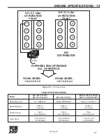
Страница 60: ... 3 FLYWHEEL END OF ENGINE ALL V 8 MODELS Rotation TUNE UP SPECIFICATIONS Model MP 5 0L 275 HP MP 8 1L STD 385 HP MP 5 7L 330 HP MP 6 0L 370 HP MP 8 1L HO 425 HP Spark Plug Type AC MR43LTS NGK PZTR5A 15 Denso TJ14R P15 Spark Plug Gap 0 060 in 0 060 in 0 060 in 1 52 mm 1 52 mm 1 52 mm Ignition Timing Fixed Fixed Fixed Not Adjustable Not Adjustable Not Adjustable Firing Order 1 8 4 3 6 5 7 2 1 8 7 2 ...

Страница 61: ...operating in salt water or brackish water areas See ENGINE MAINTENANCE NOTICE If the engine is equipped with the optional fresh water cooling system refer to draining and refilling procedures The fresh water cooling system must be serviced before fogging the engine for storage WARNING Operate the bilge blower and be sure no fuel vapors are present when treating the engine Be sure the engine compar...

Страница 62: ...mpletely drained coat the threads of the drain plugs with PerfectSeal or equivalent and reinstall in the proper locations Reinstall all the hoses and tighten the clamps securely NOTICE For additional protection against freezing and corrosion you may wish to fill the engine with antifreeze If ethylene glycol based antifreeze is used check with local environmental agencies about the proper disposal ...

Страница 63: ...ain plug 2 Remove the hose from the inlet side of the sea water pump 3 6 0L ONLY Remove the hose from the outlet side of the sea water pump 4 Crank the engine over once to purge any trapped water in the sea water pump DO NOT allow the engine to start 4 After the water has completely drained coat the threads of drain plugs with PerfectSeal or equivalent and reinstall in the proper locations Reinsta...

Страница 64: ...ttery in the boat Remove the battery and recharge in a ventilated area away from fuel vapors sparks or open flame Install the fully charged battery Be sure that all the connections are clean and free from corrosion Coat the battery terminal connections with an anti corrosion battery terminal spray Refer to the OPERATING INSTRUCTIONS section and perform all the safety checks before starting the eng...

Страница 65: ...he battery cables and connections starter circuit wiring Clean and tighten all connections Repair or replace the damaged wiring Dead Battery Recharge test and replace as necessary Engine Cranks will not Improper starting procedure Refer to STARTING start or is hard starting ENGINE in the OPERATING INSTRUCTIONS section NOTICE Battery voltage No fuel empty fuel tank Check the fuel tank level fill mu...

Страница 66: ...ooling system for leaks equipped with Fresh Water section of the cooling system Refill the system See Warning Cooling FWC systems before removing the fill cap Heat exchanger passages plugged Clean and flush the exchanger with scales and debris Improper coolant mixture Install the proper coolant mixture 50 antifreeze 50 water Insufficient engine temperature Faulty thermostat Replace the thermostat ...

Страница 67: ... pump Have fuel pump replaced by a PCM Engines Dealer Plugged or kinked fuel lines or Repair or replace the fuel lines fuel tank vent Remove obstruction Anti siphon valve faulty Clean or replace as necessary Flame arrestor dirty Clean the flame arrestor Poor engine or boat Ignition malfunction Contact PCM Engines Dealer performance Throttle not fully open Check the remote control and throttle body...

Страница 68: ...65 L510010 03 C C TROUBLESHOOTING 14 This Page Was Intentionally Left Blank ...

Страница 69: ...66 L510010 03 C C Figure 15 1 Raw Water Cooling System 5 0 5 7L Belt Driven Raw Water Pump RAW WATER FLOW Drain Locations Knock Sensor Torque 20 N m 15 lb ft WATER FLOW DIAGRAMS 15 ...

Страница 70: ...67 L510010 03 C C Figure 15 2 Fresh Water Cooling System 5 0 5 7L WATER FLOW DIAGRAMS 15 RAW WATER FLOW FRESH WATER FLOW To Cylinder Block To Cylinder Block From Intake Manifold Drain Locations ...

Страница 71: ...cessories i e heaters hot water tanks at this location IMPORTANT Accessory i e heater hot water tank Hook Up A tee may be inserted anywhere in the specified hose for most appropriate routing HOSE 1 Water OUT to heater or hot water tank HOSE 2 Water RETURN from heater or hot water tank FRESH WATER FLOW A A 2 1 1 1 1 2 2 2 2 2 2 7 Drain Locations Remove Hose from raw water pump and drain hose comple...

Страница 72: ...69 L510010 03 C C Figure 15 4 Raw Water Cooling System 8 1L RAW WATER FLOW Drain Locations WATER FLOW DIAGRAMS 15 ...

Страница 73: ...70 L510010 03 C C Figure 15 5 Fresh Water Cooling System 8 1L To Engine Block To Engine Block RAW WATER FLOW FRESH WATER FLOW Drain Locations WATER FLOW DIAGRAMS 15 ...

Страница 74: ...URE TAN 4 ENGINE ALARM TAN BLACK 5 IGNITION PURPLE WHITE 6 BATTERY RED WHITE 7 STARTER YELLOW RED 8 OIL PRESSURE LT BLUE 9 CHECK ENGINE LIGHT BROWN WHITE 10 DATA LINE ORANGE BLACK NOTE ENGINE HARNESS WIRED FOR PANELS USING VOLTMETERS ONLY NOTE A POWER FOR A FUSED ACCESSORY PANEL MAY BE TAKEN FROM THIS LOCATION LOAD CANNOT EXCEED 30 AMPS WIRE HARNESS COLOR CHART 10 4 3 2 ENGINE HARNESS 5 6 7 9 8 1 ...

Страница 75: ...and reassembly instructions Troubleshooting and maintenance charts are also included 2 PARTS Parts manuals with exploded views for service parts are available for all current engine models IMPORTANT When contacting the factory for service information be sure to include your engine model and serial number to insure the service information you receive is correct PCM Engines Pleasurecraft Engine Grou...

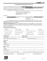
Страница 76: ...eration of the engine and finds it to be performing properly All terms in the Limited Warranty located in the Engine Owners Manual still apply PRE DELIVERY POINTS CHECKLIST TECHNICIAN TO CHECK ALL POINTS AND SIGN BELOW ___ ENGINE OIL ___SHAFT ALIGNMENT ___TIMING ___DRIVE LUBE ___CONTROL ADJUSTMENTS ___EXHAUST HOSES CLAMPS ___BATTERY CHARGE AND LEVEL ___CONTROL TRAVEL ___ALTERNATOR CHARGE ___TIGHTE...

Страница 77: ...nd later model year engines offered transferable warranty Does not apply to any earlier model Special 25th Anniversary Edition PCM Ford GT 40 engines have a fourth year of product protection on all internal engine components supplied by Ford Power Products PCM OWNERSHIP CHANGE NOTICE If you are the new owner of a Pleasurecraft Marine Engine on which the warranty has expired and would like to infor...

Страница 78: ...CE LOG Engine Port Drive Port Ignition Key Port Model and Serial Stbd Serial Stbd Number Stbd Fire Extinguisher Checked Batteries Tested Gal of Qts of Oil Oil Check Lay Up Launch Runs Made Date Fuel Port Stbd Miles Hours Change Drive Date Date Remarks ...

Страница 79: ...l this form to Pleasurecraft Marine PO Box 369 Little Mountain SC 29075 Engine Model Engine Serial Number Gear Serial Number Owner Information Name Telephone Address City State Zip Selling Dealer Dealers Address Date of Purchase Boat Make Length Type Gentlemen I would like to inform you of a problem I have experienced with the above engine My problem is My boat is located at Address Telephone City...

Страница 80: ...77 L510010 03 C C NOTES 19 ...

Страница 81: ...78 L510010 03 C C NOTES 19 ...

Страница 82: ...79 L510010 03 C C NOTES 19 ...

Страница 83: ...Pleasurecraft Engine Group 1737 Highway 76 East Little Mountain SC 29075 ...

Отзывы: