PCE Instruments PCE-VE 700 Скачать руководство пользователя страница 18

3  Cleaning

3.1  Cleaning of the Controller

en

Instructions For Use  

LED BORESCOPE PCE-VE 700

  |  17 - Feb - 2016  |  Version: 0

Page 18 of 28

3

Cleaning

3.1

Cleaning of the Controller

Cleaning the controller
NOTICE!

 The controller should only be wiped down using a damp cloth. Excess

cleaning solution can come into contact with the electrical parts and damage the
controller. Do not use wet sponges or cloths. Do not immerse the device in any
fluid.

Proceed as follows:

1. Switch the controller off and disconnect it from the power supply.
2. Cleaning the device.

Wipe the external surfaces with a soft wipe. Use a slightly dampened cloth
that has been moistened with water, a mild soap solution or isopropyl alcohol.
Stubborn stains can be removed with a mild, ammonia-based detergent.
Do not use abrasives or solvents, since such agents may damage the paint
and the labeling on the front panel.

3. Do not turn the controller back on until it is completely dry.

Completed!

3.2

Cleaning of the Camera Head and Cable

Cleaning the camera head
NOTICE!

 Do not immerse the camera plug in any fluid.

Proceed as follows:

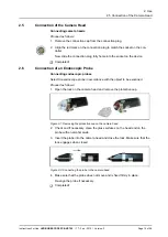
1. Disconnect the camera cable from the controller, and use the protective cap to

cover the connection plug.

2. Clean the components.

Wipe the external surfaces with a soft wipe. Use a mild cleaning agent. Do not
use any abrasive materials or solvents.
Remove any debris or soiling from optical surfaces using a swab dipped in al-
cohol (70 % ethanol).

3. Dry the components with a soft cloth.

Connect the device to the controller only after it is completely dry.

Completed!

Содержание PCE-VE 700

Страница 1: ...FL 33458 USA From outside US 1 Tel 561 320 9162 Fax 561 320 9176 info pce americas com www pce instruments com english www pce instruments com PCE Instruments UK Ltd Units 12 13 Southpoint Business Pa...

Страница 2: ...Instructions For Use LED BORESCOPE PCE VE 700 17 Feb 2016 Version 0 Page 2 of 28 TPA500 PCE 00 Version 0 2016 Feb 17...

Страница 3: ...mation on the Nameplate 11 1 6 Service Department Contact Details 11 2 Use 12 2 1 Handling Endoscopic Probes 12 2 2 Installation and Connecting the Power Supply 12 2 3 Connection of a Monitor 13 2 4 C...

Страница 4: ...016 Version 0 Page 4 of 28 5 Product Data 24 5 1 Technical Data 24 5 1 1 Controller 24 5 1 2 Camera Head 24 5 2 Ambient Conditions 25 5 2 1 Transport and Storage Conditions 25 5 2 2 Operating Conditio...

Страница 5: ...700 These instructions for use are an integral component of the device and contain all the information required by users and operators for safe and proper use 0 2 Target Group These instructions for u...

Страница 6: ...are developed and manufactured to the highest quality standards Risks despite the high quality Although this device corresponds to the current state of the art risks could still arise during initial o...

Страница 7: ...mi flexible and flexible endoscope probes is available in different lengths and diameters for the camera system The brightness of the durable and maintenance free LED can be continuously ad justed The...

Страница 8: ...PCE VE 700 17 Feb 2016 Version 0 Page 8 of 28 1 4 2 Visual Overview Camera Head Figure 1 1 Camera head 1 Camera head 2 Focusing 3 Controller CCU connection cable 4 LED light source 5 FlexiLock Lock fo...

Страница 9: ...r Use LED BORESCOPE PCE VE 700 17 Feb 2016 Version 0 Page 9 of 28 Controller Front View Figure 1 2 Front view of the controller 10 ON OFF switch 11 Window function 12 Gain control 13 White balance 14...

Страница 10: ...Use LED BORESCOPE PCE VE 700 17 Feb 2016 Version 0 Page 10 of 28 Controller Rear View Figure 1 3 Rear View of the Controller 16 Power supply connection 12 V DC 17 Service interface 18 Video output S...

Страница 11: ...heric pressure during storage 1 5 2 Information on the Nameplate This section describes the different pictograms found on the nameplate located on the underside of the device Adhere to the instruction...

Страница 12: ...reless movements particularly if the probe undergoes some kind of im pact either when it is being inserted or being tilted when it is being with drawn Damaged probes can be repaired in many cases In o...

Страница 13: ...onitor that is being used does not support S Video use the composite output and the composite cable that came with the controller Note The S video connection provides the best image quality 2 If neces...

Страница 14: ...of an Endoscopic Probe Connecting endoscopic probes Select the endoscope probe in accordance with the object to be examined Proceed as follows 1 Open the lock on the camera head and remove the protect...

Страница 15: ...nitor varies depending on the probe that is used Optimize the picture display by selecting the appropriate window size Proceed as follows 1 Press the Windows button on the front of the controller A wi...

Страница 16: ...alance OK appears on the screen Completed 2 11 Setting of the Light Amplification on the Screen Setting the light amplification Adapt the screen image to a dark environment by intensifying the monitor...

Страница 17: ...con nected to on and launch the documentation software Setting window sizes 3 Set the window size when you see the endoscopic image on the monitor see section 2 8 Focus the image 4 Bring the endoscop...

Страница 18: ...n or isopropyl alcohol Stubborn stains can be removed with a mild ammonia based detergent Do not use abrasives or solvents since such agents may damage the paint and the labeling on the front panel 3...

Страница 19: ...press the tip of the probe against or past any immovable object Proceed as follows 1 Clean the probe with a soft cloth that has been slightly moistened with a cleaning solution Do not use any metal br...

Страница 20: ...the power cord NOTICE Pulling the power cable will damage it Disconnect the power at the plug 2 Detach the fuse holder with a counterclockwise quarter turn Use a screwdriv er or a coin 3 Carefully rem...

Страница 21: ...ly see Use chapter Connection cable not connected or defective Connect the camera head to the controller Check the plug for moisture If the cable is defec tive send it in for repair Monitor not tuned...

Страница 22: ...ns For Use LED BORESCOPE PCE VE 700 17 Feb 2016 Version 0 Page 22 of 28 Issue Possible Causes Fixes Check the mains connection and connect the power if necessary No operation No power supply Check the...

Страница 23: ...ease contact one of our branch offices Contact details can be found on the back of these instructions When you send in equipment please enclose as accurate a fault description as you can and note down...

Страница 24: ...ply GlobTek Inc GTM21089 1512 T3 Input Power supply 100 240 V AC 50 60 Hz max 0 5 A Output 12 V DC max 1 25 A Fuse T 800 250 V 5 x 20 mm Brightness control automatic Signal noise ratio SNR 46 dB S Vid...

Страница 25: ...is best stored either separately or in a carrying case To avoid damage keep out of direct sunlight and away from high temperatures high humidity and radiation Temperature 0 C to 50 C Relative humidit...

Страница 26: ...g the device and its components you must adhere to the applicable national regulations governing waste disposal and recycling Any product carrying this symbol must be disposed of separately through de...

Страница 27: ......

Страница 28: ...PCE Deutschland GmbH Im Langel 4 59872 Meschede Germany Telefon 49 0 2903 976 99 0 Fax 49 0 2903 976 99 29 E Mail info pce instruments com...

Отзывы: