Drawing Number: 21067
Revision: A
PIEZOELECTRIC CHARGE MODE PRESSURE SENSOR GENERAL OPERATION MANUAL
5
If thermal transients or diaphragm impingement are
concerns, use the flush mount technique only when
space or frequency response considerations preclude the
use of the recess mount installation.
In severe or pyrotechnic environments, sensor life may
be seriously curtailed when using this mounting method.
3.4
Flash Thermal Protection
Several additional steps may be taken to provide
protection from flash thermal effects. The sensor
diaphragm may be thermally insulated at the factory,
using a thin (.010 inches / 0.254 mm) coating of ablative
silicone rubber, G.E. type 580 (“A” option). Before the
insulation is applied, the surface of the diaphragm is
treated with SS4004 primer.
If more protection is required, the recess mount may be
filled with DC-4 silicone grease or its equivalent. In
place of the silicone rubber, one or more layers of black
vinyl electrical tape on the diaphragm may provide
sufficient insulation.
3.5
Miscellaneous Installation Notes
Thread adaptors, such as the Series #61, 3/8-24 or Series
#62, 1/8 NPT, provide quick installation where
mounting port diameter is not limited. Other adaptors
include Series #63 Needle Probe, and Series #64 Water-
Cooled. Adaptor use simplifies mounting procedures
and improves troubleshooting by reducing the incorrect
data that can result from improper mounting. See the
PCB General Catalog for details.
A floating clamp nut, Model 060A03 (Model 060A05
for metric), 1/4 hex, facilitates mounting and removal of
the sensor by clamping the sensor in place without
placing undue stress on the quartz element. The clamp
nut is provided with either standard (5/16-24) or metric
(M7 x 0.75) threads and is supplied along with three seal
rings.
Model 008A Hardline Cable is recommended for
operating temperatures above 500°F. This cable is
supplied in lengths up to 40 feet (12,19 m).
3.6
Cabling
Care and attention to cable attachment is essential, as the
reliability and accuracy of your system is no better than
that of the output cable. First, check that you have
ordered the correct cable type. As with sensors, no
cable can satisfy all applications. Special low-noise
cabling should be used (e.g., PCB Series 003) with high-
impedance, charge output devices.
Connect the cable to the pressure sensor. A small
amount of thread locking compound placed on the
connector prior to attachment helps secure the cable
during testing. For additional protection in harsh
environments, the connection may be sealed with
protective materials, such as silicon rubber, O-rings and
flexible heat-shrink tubing (optional).
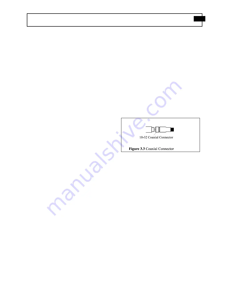
Plug the male connector on the cable into the mating
female connector on the sensor. Then, holding the
sensor stationary, secure the connector in place by
tightening down the attached cable sleeve. See Figure
3.3.
Route the cable to a charge amplifier or in-line charge
converter, making certain to strain relieve the
sensor/cable connection and minimize motion by
clamping the cable at regular intervals. Common sense
must be used to avoid physical damage and minimize
electrical noise. Avoid routing cables near high voltage
wires. Do not route cables along floors or walkways
where they may be stepped on or become contaminated.
Shielded cable should have the shield grounded at one
end only.
To dissipate any charge that may have accumulated in
the cable, short the signal to ground prior to attachment
to the charge amplifier or charge converter.


