The environment of the application is a critical
consideration during program implementation. The
sensor chosen must be capable of surviving the wide
range of conditions to which it is subjected;
therefore, take time to evaluate potential
conditions, such as high temperatures and chemical
contaminants. The specified temperature range of
the sensor must conform to the fluctuations of the
environmental temperature. If harsh industrial
chemicals are present, the sensor requires hermetic
sealing and construction that resists corrosion.
Finally, specific location of the sensor within the
environment must be sensible, as both cable and
sensor may be damaged by imprudent installation in
heavily traveled, physically punishing areas.
2.0 ICP® ACCELEROMETERS
Enclosed in the back of this guide is a Specification
Sheet, which lists the complete performance
characteristics of the particular sensor.
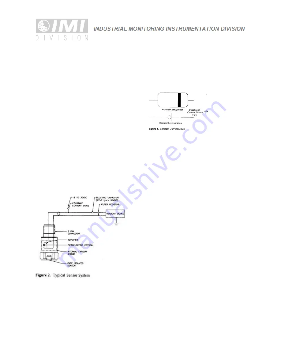
All ICP® sensors require a constant current power
source for proper operation. A typical sensing
system includes an ICP® sensor, ordinary two
conductor cable and a basic constant current power
supply (as shown in Figure 2).
The signal conditioner consists of a well-regulated 18
to 30 VDC source (battery or line-powered), a
current-regulating diode (or equivalent constant
current circuit), and a capacitor for decoupling
(removing the bias voltage) the signal.
The current-regulating device is used in place of a
resistor for several reasons. The very high dynamic
resistance of the diode yields a source follower gain
which is extremely close to unity and independent of
input voltage. Also, the diode can be changed to supply
higher currents for driving long cable lengths. Constant
current diodes, as shown in Figure 3, should be used in
ICP® signal conditioners.
(The correct orientation of the
diode within the circuit is critical for proper operation.)
Except for special models, standard ICP® sensors require
a minimum of 2 mA for proper operation.
The typical limits for this type of diode are to a 4 mA
maximum rating; however, several diodes can be placed in
parallel for higher current levels. All line-powered signal
conditioners should use higher capacity (up to 20 mA)
constant current circuits in place of the diodes, particularly
when driving long signal cables (see Section 5).
Decoupling of the data signal occurs at the output stage
of the signal conditioner. A 10 to 30 µF capacitor coupled
with a resistor shifts the signal level to essentially
eliminate the sensor bias voltage. The result is a drift-free
AC mode of operation.
3.0 OPTIONAL FEATURES
In addition to standard features, a variety of options
are also available. When listed before the model
number, the following prefix letters indicate that the
sensor is manufactured or supplied with optional
features:
CS - Canadian Standards Association Approved
Sensor
D - Dummy, non-working sensor for display purposes
EX - Cenelec Approved Sensor
FM - Factory Mutual Approval Sensor
HT - High temperature accelerometer (325
˚
F)
LB - Low Bias electronics
LC - Limited Calibration (one point calibration)
LP - Low Pass filter
M - Metric mounting hardware and cable length
U - Usable demonstration sensor (does not meet one
of more minor specifications)
VO - Velocity Output Sensors


